Information fuel-injection pump
BOSCH
9 410 618 347
9410618347
ZEXEL
104216-0010
1042160010
Rating:
Components :
| 0. | INJECTION-PUMP ASSEMBLY | 104216-0010 |
| 1. | _ | |
| 2. | FUEL INJECTION PUMP | |
| 3. | NUMBER PLATE | |
| 4. | _ | |
| 5. | CAPSULE | |
| 6. | ADJUSTING DEVICE | |
| 7. | NOZZLE AND HOLDER ASSY | |
| 8. | Nozzle and Holder | |
| 9. | Open Pre:MPa(Kqf/cm2) | |
| 10. | NOZZLE-HOLDER | |
| 11. | NOZZLE |
Scheme ###:
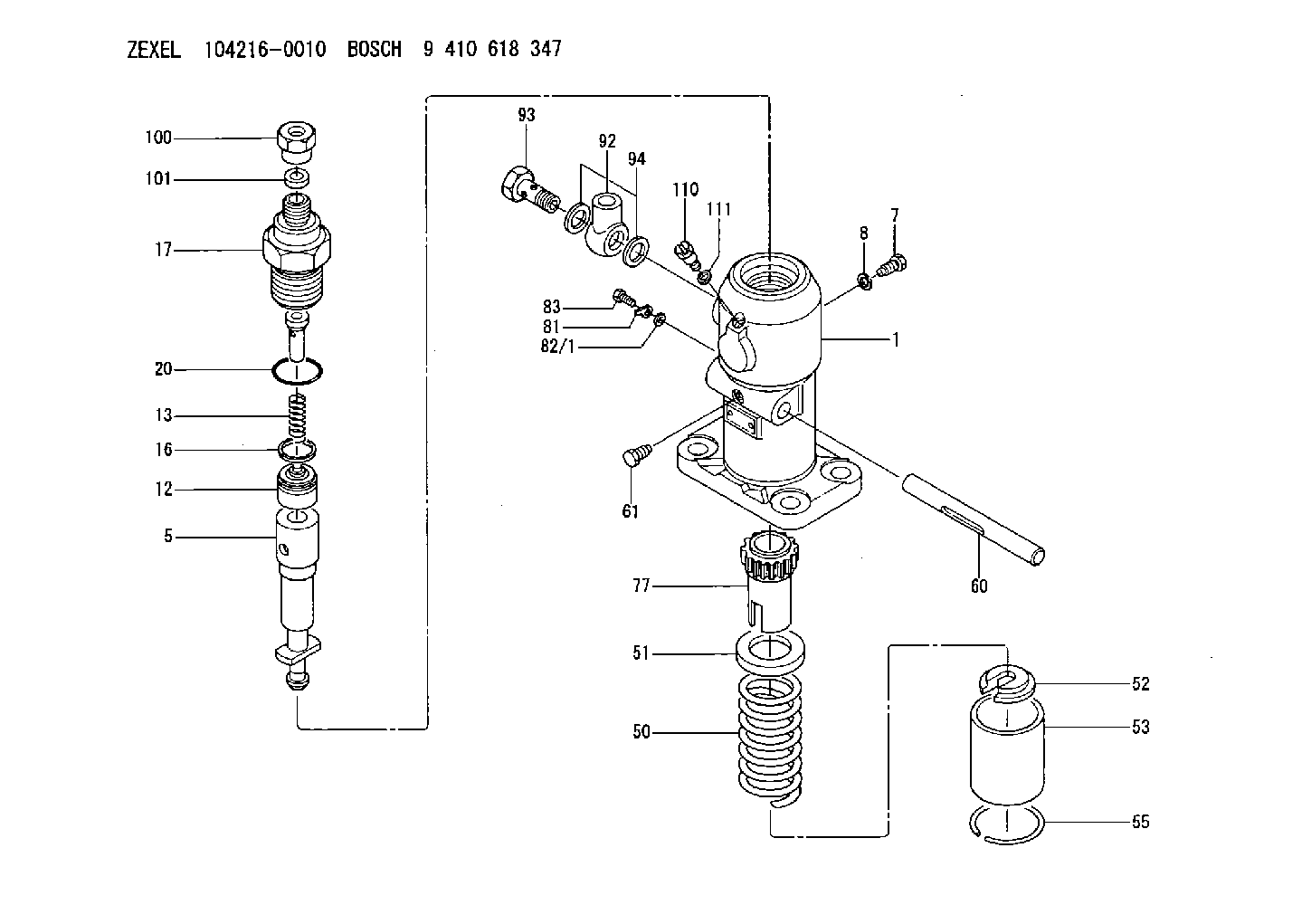
| 1. | [0] | 023500-6210 | PLAIN WASHER D11&6.4T1.5 |
| 1. | [0] | 029300-6010 | PLAIN WASHER D11&6.4T0.8 |
| 1. | [0] | 029300-6020 | PLAIN WASHER D11&6.4T0.35 |
| 1. | [1] | 141050-9620 | PUMP HOUSING |
| 5. | [1] | 141171-0620 | PLUNGER-AND-BARREL ASSY |
| 7. | [1] | 141106-8300 | CAPSULE |
| 8. | [1] | 029331-2130 | GASKET |
| 12. | [1] | 141110-5820 | DELIVERY-VALVE ASSEMBLY |
| 13. | [1] | 141112-2000 | COMPRESSION SPRING |
| 16. | [1] | 141115-4600 | GASKET |
| 17. | [1] | 141126-2420 | FITTING |
| 20. | [1] | 029635-0020 | O-RING |
| 50. | [1] | 141215-2601 | COMPRESSION SPRING |
| 51. | [1] | 141216-1800 | SLOTTED WASHER |
| 52. | [1] | 141217-3000 | SLOTTED WASHER |
| 53. | [1] | 141218-5020 | GUIDE |
| 55. | [1] | 141220-1200 | LOCKING WASHER |
| 60. | [1] | 141244-1600 | CONTROL RACK |
| 61. | [1] | 141226-3200 | BLEEDER SCREW |
| 77. | [1] | 141241-2700 | CONTROL SLEEVE |
| 81. | [1] | 141245-2000 | POINTER |
| 82/1. | [0] | 023500-6210 | PLAIN WASHER D11&6.4T1.5 |
| 82/1. | [0] | 029300-6010 | PLAIN WASHER D11&6.4T0.8 |
| 82/1. | [0] | 029300-6020 | PLAIN WASHER D11&6.4T0.35 |
| 83. | [1] | 020006-1440 | BLEEDER SCREW M6P1L14 |
| 92. | [1] | 029702-6060 | INLET UNION |
| 93. | [1] | 029732-6010 | EYE BOLT |
| 94. | [2] | 026526-3440 | GASKET |
| 100. | [1] | 029762-6130 | UNION NUT |
| 101. | [1] | 029351-7010 | PLAIN WASHER |
| 110. | [1] | 141420-1600 | BLEEDER SCREW |
| 111. | [1] | 026506-1040 | GASKET D9.9&6.2T1 |
Cross reference number
Zexel num
Bosch num
Firm num
Name
104216-0010
FUEL-INJECTION PUMP
K 24FA FUEL INJECTION PUMP PF-1GD(V) PF
K 24FA FUEL INJECTION PUMP PF-1GD(V) PF
Information:
1. Remove cylinder head assembly mounting bolts (1) and (2).
To prevent damage to the cylinder head assembly-to-spacer block dowels, keep the head assembly level during removal.
2. Fasten a hoist to the cylinder head assembly as shown. Lift the cylinder head assembly off of the spacer block. The approximate weight of the cylinder head is 236 kg (520 lb).3. Remove the cylinder head assembly gasket from the spacer block. The following steps are for the installation of the cylinder head assembly.4. Thoroughly clean the mating surfaces of the cylinder head assembly and the spacer block.5. Install the head gasket on the spacer block.6. Fasten a hoist to the cylinder head assembly. Position the cylinder head assembly on the dowels in the spacer block. Lower the cylinder head assembly onto the spacer block.7. Put clean engine oil on the threads of bolts (1) and (2) that hold the cylinder head assembly in position. Install bolts (1) and (2).
Cylinder Head Assembly Tightening Sequence8. Tighten cylinder head assembly mounting bolts (1) and (2) as follows:a. Put 2P2506 Thread Lubricant on the threads of bolts (1) and (2).b . Tighten bolts 1 through 26 in numerical sequence shown to a torque of 150 15 N m (110 11 lb ft).c. Tighten bolts 1 through 26 in numerical sequence shown to a torque of 275 15 N m (200 11 lb ft).d. Retorque bolts 1 through 26 in numerical sequence shown to 275 15 N m (200 11 lb ft).e. Tighten bolts 27 through 33 in numerical sequence shown to a torque of 25 7 N m (18 5 lb ft).End By:a. install valve cover baseb. install (EUI) fuel injectorsc. install rocker arm assemblies and push rodsd. install water outlet manifolde. install exhaust manifold