Information fuel-injection pump
BOSCH
9 410 617 815
9410617815
ZEXEL
104215-3060
1042153060
Rating:
Components :
| 0. | INJECTION-PUMP ASSEMBLY | 104215-3060 |
| 1. | _ | |
| 2. | FUEL INJECTION PUMP | |
| 3. | NUMBER PLATE | |
| 4. | _ | |
| 5. | CAPSULE | |
| 6. | ADJUSTING DEVICE | |
| 7. | NOZZLE AND HOLDER ASSY | |
| 8. | Nozzle and Holder | |
| 9. | Open Pre:MPa(Kqf/cm2) | |
| 10. | NOZZLE-HOLDER | |
| 11. | NOZZLE |
Scheme ###:
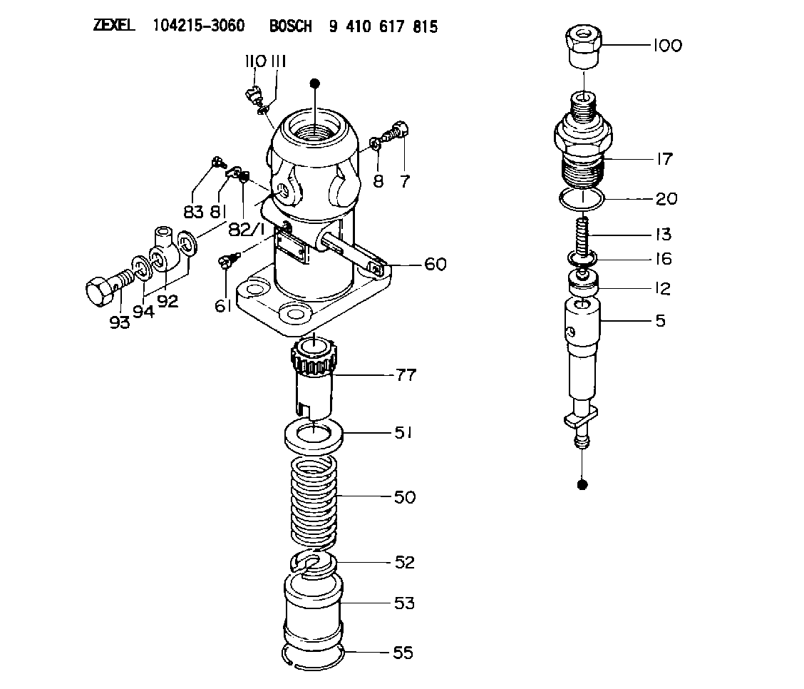
| 5. | [1] | 141171-0520 | PLUNGER-AND-BARREL ASSY |
| 7. | [1] | 141106-8300 | CAPSULE |
| 8. | [1] | 029331-2130 | GASKET |
| 12. | [1] | 141110-3020 | DELIVERY-VALVE ASSEMBLY |
| 13. | [1] | 141112-2000 | COMPRESSION SPRING |
| 16. | [1] | 141115-4600 | GASKET |
| 17. | [1] | 141126-4620 | FITTING |
| 20. | [1] | 029635-0020 | O-RING |
| 50. | [1] | 141215-2601 | COMPRESSION SPRING |
| 51. | [1] | 141216-1800 | SLOTTED WASHER |
| 52. | [1] | 141217-3000 | SLOTTED WASHER |
| 53. | [1] | 141218-5020 | GUIDE |
| 55. | [1] | 141220-1200 | LOCKING WASHER |
| 60. | [1] | 141243-4000 | CONTROL RACK |
| 61. | [1] | 141226-3200 | BLEEDER SCREW |
| 77. | [1] | 141241-2700 | CONTROL SLEEVE |
| 81. | [1] | 141245-2000 | POINTER |
| 82/1. | [0] | 023500-6210 | PLAIN WASHER D11&6.4T1.5 |
| 82/1. | [0] | 029300-6010 | PLAIN WASHER D11&6.4T0.8 |
| 82/1. | [0] | 029300-6020 | PLAIN WASHER D11&6.4T0.35 |
| 83. | [1] | 020006-1440 | BLEEDER SCREW M6P1L14 |
| 92. | [1] | 029702-6020 | INLET UNION |
| 93. | [1] | 029732-6010 | EYE BOLT |
| 94. | [2] | 026526-3440 | GASKET |
| 100. | [1] | 029762-6140 | UNION NUT |
| 110. | [1] | 141420-1600 | BLEEDER SCREW |
| 111. | [1] | 026506-1040 | GASKET D9.9&6.2T1 |
Cross reference number
Zexel num
Bosch num
Firm num
Name
104215-3060
FUEL-INJECTION PUMP
K 24FA FUEL INJECTION PUMP PF-1GD(V) PF
K 24FA FUEL INJECTION PUMP PF-1GD(V) PF
Information:
At operating temperature, the engine cooling system is hot and under pressure. Steam can cause personal injury. Check the coolant level only after the engine has been stopped and the fill cap on the radiator is cool enough to touch with your bare hand. Remove the fill cap slowly to relieve pressure. Cooling system conditioner contains alkali. Avoid contact with skin and eyes to prevent personal injury.
1. Drain the coolant from the cooling system into a suitable container for disposal.2. Remove the top radiator hose. 3. Remove four bolts (1) and the washers. Remove regulator housing (2) and the water temperature regulator as a unit. 4. Remove regulator housing gasket (4) from the regulator housing. Remove water temperature regulator (3).5. Remove the lip-type seal from the regulator housing. The following steps are for the installation of the water temperature regulator.6. Install the lip-type seal in the regulator housing with tool (A). Install the lip facing in toward the inside of the housing and until it makes contact with the counterbore in the housing. Lubricate the lip seal with glycerin.7. Install water temperature regulator (3) in the regulator housing.8. Put gasket (4) and regulator housing (2) in position, and install the four washers and bolts (1) that hold it.9. Connect the top radiator hose to the regulator housing.10. Fill the cooling system with coolant to the correct level. See the Operation & Maintenance Manual for the correct filling procedure.