Information fuel-injection pump
BOSCH
9 410 618 121
9410618121
ZEXEL
104214-0181
1042140181
Rating:
Components :
| 0. | INJECTION-PUMP ASSEMBLY | 104214-0181 |
| 1. | _ | |
| 2. | FUEL INJECTION PUMP | |
| 3. | NUMBER PLATE | |
| 4. | _ | |
| 5. | CAPSULE | |
| 6. | ADJUSTING DEVICE | |
| 7. | NOZZLE AND HOLDER ASSY | |
| 8. | Nozzle and Holder | |
| 9. | Open Pre:MPa(Kqf/cm2) | |
| 10. | NOZZLE-HOLDER | |
| 11. | NOZZLE |
Scheme ###:
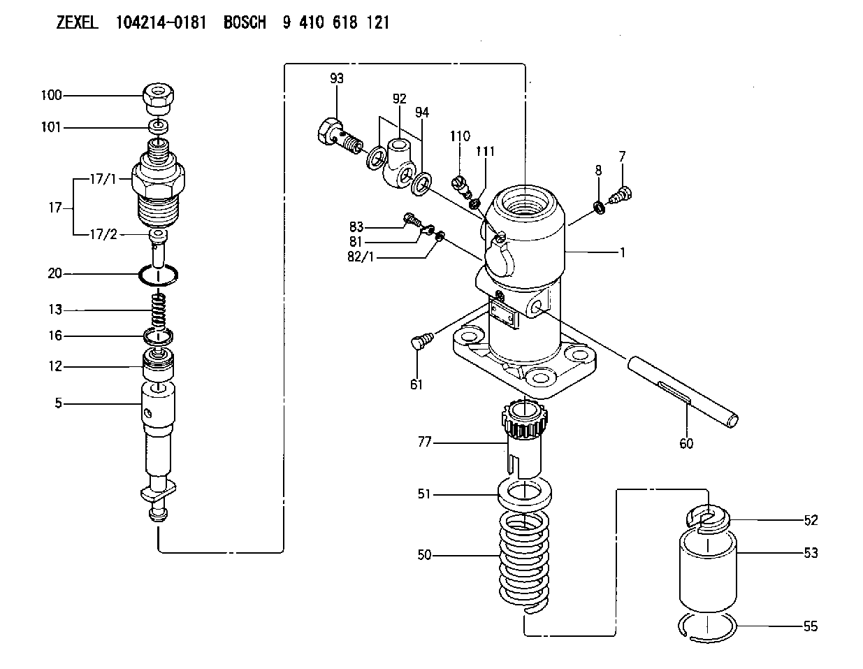
| 1. | [1] | 141050-9620 | PUMP HOUSING |
| 5. | [1] | 141171-0420 | PLUNGER-AND-BARREL ASSY |
| 7. | [1] | 141106-8300 | CAPSULE |
| 8. | [1] | 029331-2130 | GASKET |
| 12. | [1] | 141140-6521 | DELIVERY-VALVE ASSEMBLY |
| 13. | [1] | 141112-2000 | COMPRESSION SPRING |
| 16. | [1] | 141115-4600 | GASKET |
| 17. | [1] | 141126-2420 | FITTING |
| 17/1. | [1] | 141126-2400 | FITTING |
| 17/2. | [1] | 141117-3100 | FILLER PIECE |
| 20. | [1] | 029635-0020 | O-RING |
| 50. | [1] | 141215-2601 | COMPRESSION SPRING |
| 51. | [1] | 141216-1800 | SLOTTED WASHER |
| 52. | [1] | 141217-3000 | SLOTTED WASHER |
| 53. | [1] | 141218-5020 | GUIDE |
| 55. | [1] | 141220-1200 | LOCKING WASHER |
| 60. | [1] | 141244-1600 | CONTROL RACK |
| 61. | [1] | 141226-3200 | BLEEDER SCREW |
| 77. | [1] | 141241-2700 | CONTROL SLEEVE |
| 81. | [1] | 141245-2000 | POINTER |
| 82/1. | [0] | 023500-6210 | PLAIN WASHER D11&6.4T1.5 |
| 82/1. | [0] | 029300-6010 | PLAIN WASHER D11&6.4T0.8 |
| 82/1. | [0] | 029300-6020 | PLAIN WASHER D11&6.4T0.35 |
| 83. | [1] | 020006-1440 | BLEEDER SCREW M6P1L14 |
| 92. | [1] | 029702-6020 | INLET UNION |
| 93. | [1] | 029732-6010 | EYE BOLT |
| 94. | [2] | 026526-3440 | GASKET |
| 100. | [1] | 029762-6130 | UNION NUT |
| 101. | [1] | 029351-7010 | PLAIN WASHER |
| 110. | [1] | 141420-1600 | BLEEDER SCREW |
| 111. | [1] | 026506-1040 | GASKET D9.9&6.2T1 |
Cross reference number
Zexel num
Bosch num
Firm num
Name
104214-0181
FUEL-INJECTION PUMP
K 24FA FUEL INJECTION PUMP PF-1GD(V) PF
K 24FA FUEL INJECTION PUMP PF-1GD(V) PF
Information:
The diagnostic lamp, on the truck dashboard, can be used to communicate status or operation problems of the electronic control system.Trucks With Cruise
The dash mounted cruise switches are used to interrogate the ECM for system status. With the cruise switch in the "off" position, hold the set/resume switch in the resume position until "check engine" light begins to flash. The sequence of flashes represents the system diagnostic message. The first sequence of flashes adds up to the first digit of the fault code. After a one second pause, a second sequence of flashes will occur which represents the second digit of the fault code. Any additional fault codes will follow, after a pause, and will be displayed in the same manner.Trucks Without Cruise
If cruise control switches are not installed or if their configuration (such as a GM type switch) does not permit their usage for checking diagnostic codes, then a push button momentary ON switch should be installed between Pin 3 of the vehicle connector P7 and engine ground.Faults With Throttle Response
The vehicle should be driven to a dealer for service ONLY if the engine oil pressure gauge indicates normal engine oil pressure and engine fuel pressure is within the normal range.Faults Without Throttle Response
If the check engine light is on and the engine does not respond to changes in throttle position, the vehicle should be driven to a dealer ONLY if the oil pressure gauge indicates normal engine oil pressure and engine fuel pressure is within the normal range.If equipped, turn on the cruise on/off switch and operate the vehicle using the set/resume cruise control switch to raise and lower the engine rpm.The cruise control mode is operational from 0 km/h (mph) up to the vehicle speed limit (VSL) when the 3406B (PEEC III) control unit does not respond to changes in throttle position. Maximum engine rpm will be the programmed engine rpm at the vehicle speed limit (VSL). Cruise control must be reselected after each gear change.