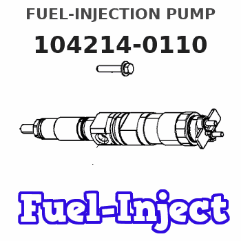
Information fuel-injection pump
BOSCH
9 410 617 494
9410617494
ZEXEL
104214-0110
1042140110
NIIGATA-URAWA
12147000A
12147000a
Rating:
Components :
| 0. | INJECTION-PUMP ASSEMBLY | 104214-0110 |
| 1. | _ | |
| 2. | FUEL INJECTION PUMP | |
| 3. | NUMBER PLATE | |
| 4. | _ | |
| 5. | CAPSULE | |
| 6. | ADJUSTING DEVICE | |
| 7. | NOZZLE AND HOLDER ASSY | |
| 8. | Nozzle and Holder | |
| 9. | Open Pre:MPa(Kqf/cm2) | |
| 10. | NOZZLE-HOLDER | |
| 11. | NOZZLE |
Scheme ###:
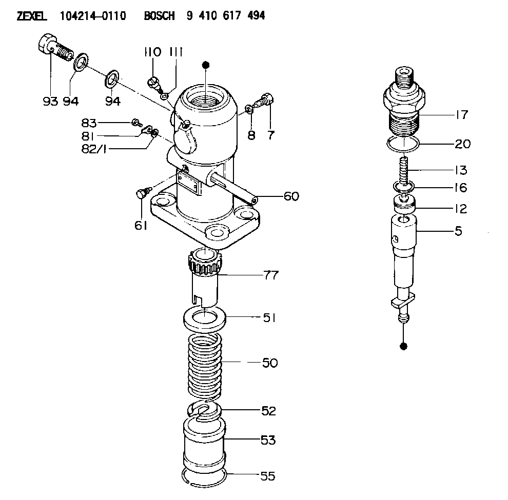
| 5. | [1] | 141171-3720 | PLUNGER-AND-BARREL ASSY |
| 7. | [1] | 141106-8300 | CAPSULE |
| 8. | [1] | 029331-2130 | GASKET |
| 12. | [1] | 141110-6420 | DELIVERY-VALVE ASSEMBLY |
| 13. | [1] | 141112-2000 | COMPRESSION SPRING |
| 16. | [1] | 141115-4600 | GASKET |
| 17. | [1] | 141126-2420 | FITTING |
| 20. | [1] | 029635-0020 | O-RING |
| 50. | [1] | 141215-2601 | COMPRESSION SPRING |
| 51. | [1] | 141216-1800 | SLOTTED WASHER |
| 52. | [1] | 141217-3000 | SLOTTED WASHER |
| 53. | [1] | 141218-5020 | GUIDE |
| 55. | [1] | 141220-1200 | LOCKING WASHER |
| 60. | [1] | 141244-3400 | CONTROL RACK |
| 61. | [1] | 141226-3200 | BLEEDER SCREW |
| 77. | [1] | 141241-2700 | CONTROL SLEEVE |
| 81. | [1] | 141245-2000 | POINTER |
| 82/1. | [0] | 023500-6210 | PLAIN WASHER D11&6.4T1.5 |
| 82/1. | [0] | 029300-6010 | PLAIN WASHER D11&6.4T0.8 |
| 82/1. | [0] | 029300-6020 | PLAIN WASHER D11&6.4T0.35 |
| 83. | [1] | 020006-1440 | BLEEDER SCREW M6P1L14 |
| 93. | [1] | 029732-6010 | EYE BOLT |
| 94. | [2] | 026526-3440 | GASKET |
| 94. | [2] | 026526-3440 | GASKET |
| 110. | [1] | 141420-1600 | BLEEDER SCREW |
| 111. | [1] | 026506-1040 | GASKET D9.9&6.2T1 |
Cross reference number
Zexel num
Bosch num
Firm num
Name
104214-0110
12147000A NIIGATA-URAWA
FUEL-INJECTION PUMP
K 24FA FUEL INJECTION PUMP PF-1GD(V) PF
K 24FA FUEL INJECTION PUMP PF-1GD(V) PF
Information:
1. Drain the coolant and oil from the engine.2. Remove bolt (1) and retainer (2) that hold the oil lines in the BrakeSaver control valve. 3. Disconnect oil lines (3) and (4) from the oil cooler. Remove oil lines (3) and (4) from the BrakeSaver control valve.4. Fasten a hoist to the oil cooler. 5. Remove two bolts (8) to disconnect elbow (10) from front bonnet (9). Remove two bolts (7) to disconnect front bonnet (9) from the water pump.6. Remove four bolts (5) to disconnect the rear bonnet from the cylinder block. Disconnect bracket (12).7. Remove oil cooler (11), front bonnet (9) and rear bonnet (6) from the engine as a unit. The weight is approximately 54 kg (120 lb.).8. Make a separation of front bonnet (9) and rear bonnet (6) from oil cooler (11). 9. Clean oil cooler core tubes (13) with a 3.81 mm (.150 in.) diameter rod.10. Inspect all O-ring seals and gaskets for damage, and make replacements if needed. Put clean engine oil on the O-ring seals.11. Install rear bonnet (6) and front bonnet (9) on oil cooler (11).12. Fasten a hoist, and put the oil cooler and bonnets as a unit in place on the engine. Connect bracket (12) but do not tighten the bolts at this time.13. Install the gasket and four bolts (5) that hold rear bonnet (6) to the engine block. Do not tighten the bolts at this time.14. Install the gasket and two bolts (7) that hold front bonnet (9) to the water pump. Do not tighten the bolts at this time.15. Install the gasket and bolts (8) that hold elbow (10) to the front bonnet. Tighten all the bolts.16. Make sure the O-ring seals are in place on the oil lines, and install oil lines (3) and (4).17. Install retainer (2) to hold the oil lines in the BrakeSaver control valve. If the bottom plug in the oil pan was removed, put the split (seam) of the gasket for the plug against the oil pan. If either plug on the side of the oil pan was removed, put 5P3413 Thread Sealant With Teflon on the threads, and tighten the plug to a torque of 80 11 N m (60 8 lb.ft.).18. Fill the engine with coolant and oil. See the Maintenance Manual.