Information fuel-injection pump
BOSCH
9 410 617 493
9410617493
ZEXEL
104214-0061
1042140061
NIIGATA-TEKKOU
10247000C
10247000c
Rating:
Components :
| 0. | INJECTION-PUMP ASSEMBLY | 104214-0061 |
| 1. | _ | |
| 2. | FUEL INJECTION PUMP | |
| 3. | NUMBER PLATE | |
| 4. | _ | |
| 5. | CAPSULE | |
| 6. | ADJUSTING DEVICE | |
| 7. | NOZZLE AND HOLDER ASSY | |
| 8. | Nozzle and Holder | |
| 9. | Open Pre:MPa(Kqf/cm2) | |
| 10. | NOZZLE-HOLDER | |
| 11. | NOZZLE |
Scheme ###:
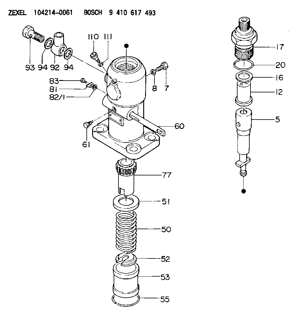
| 5. | [1] | 141171-1820 | PLUNGER-AND-BARREL ASSY |
| 7. | [1] | 141106-8300 | CAPSULE |
| 8. | [1] | 029331-2130 | GASKET |
| 12. | [1] | 141142-8820 | DELIVERY-VALVE ASSEMBLY |
| 16. | [1] | 141115-4600 | GASKET |
| 17. | [1] | 141136-8200 | FITTING |
| 20. | [1] | 029635-0020 | O-RING |
| 50. | [1] | 141215-2601 | COMPRESSION SPRING |
| 51. | [1] | 141216-1800 | SLOTTED WASHER |
| 52. | [1] | 141217-3000 | SLOTTED WASHER |
| 53. | [1] | 141218-5020 | GUIDE |
| 55. | [1] | 141220-1200 | LOCKING WASHER |
| 60. | [1] | 141243-3900 | CONTROL RACK |
| 61. | [1] | 141226-3200 | BLEEDER SCREW |
| 77. | [1] | 141241-2700 | CONTROL SLEEVE |
| 81. | [1] | 140245-0200 | POINTER |
| 82/1. | [0] | 023500-6210 | PLAIN WASHER D11&6.4T1.5 |
| 82/1. | [0] | 029300-6010 | PLAIN WASHER D11&6.4T0.8 |
| 82/1. | [0] | 029300-6020 | PLAIN WASHER D11&6.4T0.35 |
| 83. | [1] | 021006-1420 | FLAT-HEAD SCREW |
| 92. | [1] | 029702-6020 | INLET UNION |
| 93. | [1] | 029732-6010 | EYE BOLT |
| 94. | [2] | 026526-3440 | GASKET |
| 94. | [2] | 026526-3440 | GASKET |
| 110. | [1] | 140420-0600 | BLEEDER SCREW |
| 111. | [1] | 026506-1040 | GASKET D9.9&6.2T1 |
Cross reference number
Zexel num
Bosch num
Firm num
Name
9 410 617 493
10247000C NIIGATA-TEKKOU
FUEL-INJECTION PUMP
* K 24FA PF-1GD(V) PF
* K 24FA PF-1GD(V) PF
Information:
Start By:a. remove oil pump1. Check the main bearing caps for identification for their location and direction in the block. The caps must be installed in the same location and direction from which they were removed. 2. Remove No. 2 through No. 6 bearing caps (1). Remove thrust plates from the No. 4 main bearing.
If the crankshaft is turned in the wrong direction, the tab of the bearing will be pushed between the crankshaft and cylinder block. This can cause damage to either the crankshaft or cylinder block or both.
3. Remove the upper halves of the main bearings by putting tool (A) in oil hole (2) in the crankshaft. Turn the crankshaft in the direction which will push the