Information fuel-injection pump
BOSCH
9 410 617 811
9410617811
ZEXEL
104213-3150
1042133150
Rating:
Components :
| 0. | INJECTION-PUMP ASSEMBLY | 104213-3150 |
| 1. | _ | |
| 2. | FUEL INJECTION PUMP | |
| 3. | NUMBER PLATE | |
| 4. | _ | |
| 5. | CAPSULE | |
| 6. | ADJUSTING DEVICE | |
| 7. | NOZZLE AND HOLDER ASSY | |
| 8. | Nozzle and Holder | |
| 9. | Open Pre:MPa(Kqf/cm2) | |
| 10. | NOZZLE-HOLDER | |
| 11. | NOZZLE |
Scheme ###:
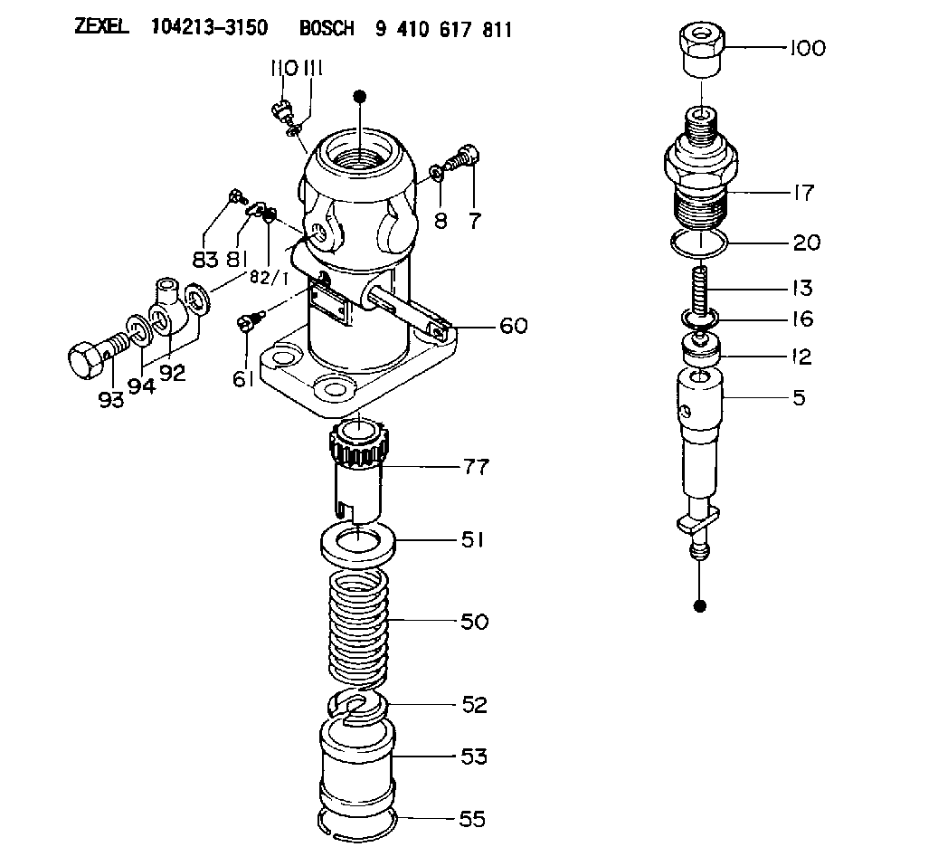
| 5. | [1] | 141171-0320 | PLUNGER-AND-BARREL ASSY |
| 7. | [1] | 141106-8300 | CAPSULE |
| 8. | [1] | 029331-2130 | GASKET |
| 12. | [1] | 141140-3220 | DELIVERY-VALVE ASSEMBLY |
| 13. | [1] | 141112-2000 | COMPRESSION SPRING |
| 16. | [1] | 141115-4600 | GASKET |
| 17. | [1] | 141126-2620 | FITTING |
| 20. | [1] | 029635-0020 | O-RING |
| 50. | [1] | 141215-2601 | COMPRESSION SPRING |
| 51. | [1] | 141216-1800 | SLOTTED WASHER |
| 52. | [1] | 141217-3000 | SLOTTED WASHER |
| 53. | [1] | 141218-5020 | GUIDE |
| 55. | [1] | 141220-1200 | LOCKING WASHER |
| 60. | [1] | 141243-4000 | CONTROL RACK |
| 61. | [1] | 141226-3200 | BLEEDER SCREW |
| 77. | [1] | 141241-6100 | CONTROL SLEEVE |
| 81. | [1] | 141245-2000 | POINTER |
| 82/1. | [0] | 023500-6210 | PLAIN WASHER D11&6.4T1.5 |
| 82/1. | [0] | 029300-6010 | PLAIN WASHER D11&6.4T0.8 |
| 82/1. | [0] | 029300-6020 | PLAIN WASHER D11&6.4T0.35 |
| 83. | [1] | 020006-1440 | BLEEDER SCREW M6P1L14 |
| 92. | [1] | 029702-6020 | INLET UNION |
| 93. | [1] | 029732-6010 | EYE BOLT |
| 94. | [2] | 026526-3440 | GASKET |
| 100. | [1] | 029762-6140 | UNION NUT |
| 110. | [1] | 141420-1600 | BLEEDER SCREW |
| 111. | [1] | 026506-1040 | GASKET D9.9&6.2T1 |
Cross reference number
Zexel num
Bosch num
Firm num
Name
104213-3150
FUEL-INJECTION PUMP
K 24FA FUEL INJECTION PUMP PF-1GD(V) PF
K 24FA FUEL INJECTION PUMP PF-1GD(V) PF
Information:
Start By:a. remove fuel injection linesb. remove rack actuator package
Out Of Chassis
In Chassis1. Remove the plug, and move the rack until tool (A) can be installed to hold the rack in the center position. The rack must be in the center position to remove the fuel injection pumps.
To prevent possible personal injury carefully follow the steps below.
2. Put tooling (B), except for the 8S4613 Wrench, in position on the fuel pump housing as shown. Lower the handle to center the adjusting screw with the fuel line seat. With the handle down in the locked position, the adjusting screw must just be in contact with fuel line seat (1). If force is needed to lower the handle or there is a gap, remove the tooling, and make an adjustment to the screw.3. Loosen bushing (2) 1/4 of a turn.4. Put tooling (B) in position on the pump housing with the handle down in the locked position as shown.5. Remove bushing (2) from the pump housing.6. Carefully and slowly lift the handle to release the spring force. Remove the tooling. 7. Install tool (C) on fuel pump (4) as shown.8. Remove seal (3) and fuel pump (4) from the fuel pump housing. 9. Remove spacers (5) from the pump housing. There must be a pump installed on either side of the pump to be removed to install tooling (B). If there is no pump, take a pump already removed, and remove the spring so there will be no spring force, and install it in the pump housing. See Install Fuel Pump. Spacers (5) are the same thickness for each fuel injection pump so they can be mixed. The fuel injection pump plungers and barrels are sets and cannot be mixed.Install Fuel Injection Pumps
1. Install spacers (5) in the fuel pump housing.2. Move the rack until tool (A) can be installed to hold the rack in the center position. The rack must be in the center position to install the fuel injection pumps.3. Install a fuel pump without its spring so that tool (B) can be installed. See Step 5 for correct fuel pump installation. 4. Install tool (C) on the bonnet of the fuel pump as shown.5. Install the fuel pump in the pump housing with the saw cut (slot) (9) in the gear in alignment with small pin (6) in the lifter assembly and groove (8) in the barrel in alignment with large pin (7) in the pump housing. 6. Install the seal and bushing (2) on the fuel pump.7. Put tooling (B) in position on the fuel pump housing as shown.8. Lower the handle slowly and carefully. If the fuel pump is not installed correctly, the handle will not go all the way down. Do not try to use force on it. Remove and install the tooling and the fuel pump again.9. Make sure the seal is in its correct position, and start to tighten bushing (2). Remove the tooling, and tighten the bushing to a torque of