Information fuel-injection pump
BOSCH
9 410 617 489
9410617489
ZEXEL
104213-3130
1042133130
NIIGATA-URAWA
73447000C
73447000c
Rating:
Components :
| 0. | INJECTION-PUMP ASSEMBLY | 104213-3130 |
| 1. | _ | |
| 2. | FUEL INJECTION PUMP | |
| 3. | NUMBER PLATE | |
| 4. | _ | |
| 5. | CAPSULE | |
| 6. | ADJUSTING DEVICE | |
| 7. | NOZZLE AND HOLDER ASSY | |
| 8. | Nozzle and Holder | |
| 9. | Open Pre:MPa(Kqf/cm2) | |
| 10. | NOZZLE-HOLDER | |
| 11. | NOZZLE |
Scheme ###:
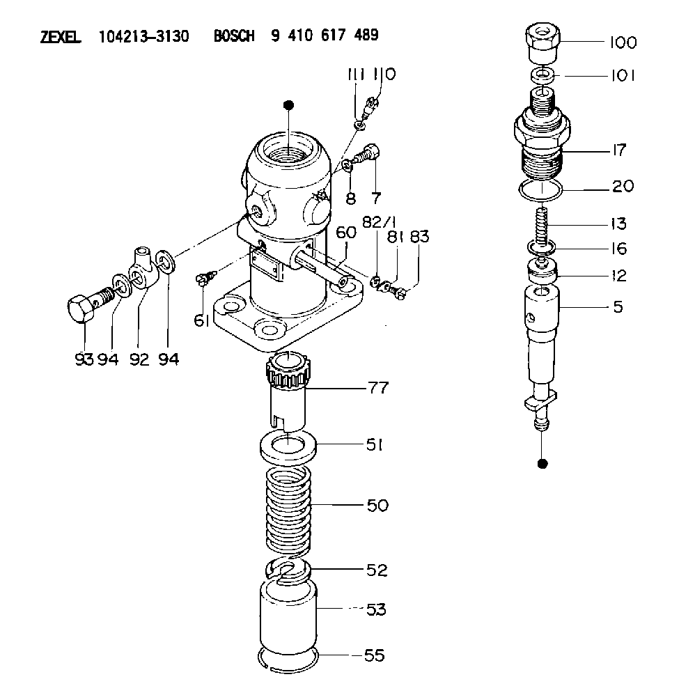
| 5. | [1] | 141171-3220 | PLUNGER-AND-BARREL ASSY |
| 7. | [1] | 141106-8300 | CAPSULE |
| 8. | [1] | 029331-2130 | GASKET |
| 12. | [1] | 141140-1220 | DELIVERY-VALVE ASSEMBLY |
| 13. | [1] | 141112-2000 | COMPRESSION SPRING |
| 16. | [1] | 141115-4600 | GASKET |
| 17. | [1] | 141126-8920 | FITTING |
| 20. | [1] | 029635-0020 | O-RING |
| 50. | [1] | 141215-2601 | COMPRESSION SPRING |
| 51. | [1] | 141216-1800 | SLOTTED WASHER |
| 52. | [1] | 141217-3000 | SLOTTED WASHER |
| 53. | [1] | 141218-5120 | GUIDE |
| 55. | [1] | 141220-1200 | LOCKING WASHER |
| 60. | [1] | 141243-8400 | CONTROL RACK |
| 61. | [1] | 141226-3200 | BLEEDER SCREW |
| 77. | [1] | 141241-2700 | CONTROL SLEEVE |
| 81. | [1] | 141245-2000 | POINTER |
| 82/1. | [0] | 023500-6210 | PLAIN WASHER D11&6.4T1.5 |
| 82/1. | [0] | 029300-6010 | PLAIN WASHER D11&6.4T0.8 |
| 82/1. | [0] | 029300-6020 | PLAIN WASHER D11&6.4T0.35 |
| 83. | [1] | 020006-1440 | BLEEDER SCREW M6P1L14 |
| 92. | [1] | 029702-6020 | INLET UNION |
| 93. | [1] | 029732-6010 | EYE BOLT |
| 94. | [2] | 026526-3440 | GASKET |
| 94. | [2] | 026526-3440 | GASKET |
| 100. | [1] | 029762-6140 | UNION NUT |
| 101. | [1] | 029351-2040 | PLAIN WASHER |
| 110. | [1] | 141420-1600 | BLEEDER SCREW |
| 111. | [1] | 026506-1040 | GASKET D9.9&6.2T1 |
Cross reference number
Zexel num
Bosch num
Firm num
Name
104213-3130
73447000C NIIGATA-URAWA
FUEL-INJECTION PUMP
K 24FA FUEL INJECTION PUMP PF-1GD(V) PF
K 24FA FUEL INJECTION PUMP PF-1GD(V) PF
104213-3130
73447000C
FUEL-INJECTION PUMP
K 24FA FUEL INJECTION PUMP PF-1GD(V) PF
K 24FA FUEL INJECTION PUMP PF-1GD(V) PF
Information:
Typical Example1. With the rear of wire connector toward you, snap tool (A) (the correct size for the wire being removed) over the wire of the contact to be removed.2. Slide tool (A) along the wire into the contact cavity until it engages the contact and resistance is felt. Do not twist or insert tool (A) at an angle.
Typical Example3. Pull contact (2) and wire assembly out of connector (1).4. Remove the damaged contact from the wire.
Typical Example5. Use tool (B) and the following procedure to secure contact (2) to the wire.a. Strip 6.3 mm (.25 in.) insulation from the wire.b. Raise selector knob (3) and rotate until arrow is aligned with the wire size to be crimped.c. Loosen locknut. Turn adjusting screw (4) in (clockwise) until it stops.
Typical Exampled. Insert contact (2) into tool (B). Turn the adjusting screw out (counter clockwise) until the contact is flush with indentor cover (5) on tool (B). Tighten locknut.
Typical Examplec. Insert wire in contact (2). The contact must be centered between the indentors. Close the handles until the handle contacts the stop.d. Release the handles and remove the crimped contact.e. Inspect the contact to insure that all wire strands are inside the crimp barrel. Look in the hole in the contact. If the crimp is correct wire strands will be visable in the hole in the contact.
Typical Example6. Grasp the wire approximately 25.4 mm (1.00 in.) behind the contact crimp barrel.7. Hold connector (1) with the rear grommet facing you.8. Push contact (2) straight into connector (1) until a positive stop is felt.9. Gently pull on the wire and connector assembly to confirm that the contact is properly locked in place.