Information fuel-injection pump
BOSCH
9 410 617 026
9410617026
ZEXEL
104213-3120
1042133120
YANMAR
14267251510
14267251510
Rating:
Components :
| 0. | INJECTION-PUMP ASSEMBLY | 104213-3120 |
| 1. | _ | |
| 2. | FUEL INJECTION PUMP | |
| 3. | NUMBER PLATE | |
| 4. | _ | |
| 5. | CAPSULE | |
| 6. | ADJUSTING DEVICE | |
| 7. | NOZZLE AND HOLDER ASSY | |
| 8. | Nozzle and Holder | |
| 9. | Open Pre:MPa(Kqf/cm2) | |
| 10. | NOZZLE-HOLDER | |
| 11. | NOZZLE | 105012-5680 |
Scheme ###:
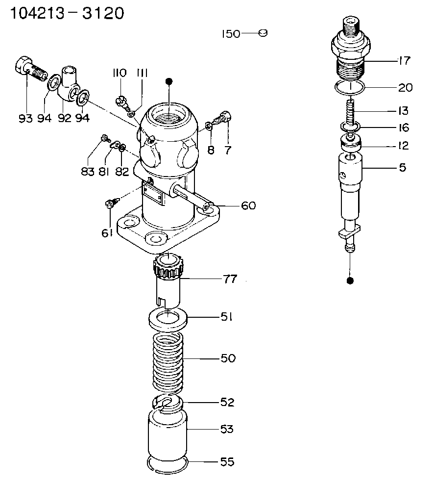
| 1. | [1] | 141052-1920 | PUMP HOUSING |
| 5. | [1] | 141171-3020 | PLUNGER-AND-BARREL ASSY |
| 7. | [1] | 141106-8300 | CAPSULE |
| 8. | [1] | 029331-2130 | GASKET |
| 12. | [1] | 141110-5820 | DELIVERY-VALVE ASSEMBLY |
| 13. | [1] | 141112-2000 | COMPRESSION SPRING |
| 16. | [1] | 141115-4600 | GASKET |
| 17. | [1] | 141126-2620 | FITTING |
| 20. | [1] | 029635-0020 | O-RING |
| 50. | [1] | 141215-2601 | COMPRESSION SPRING |
| 51. | [1] | 141216-1800 | SLOTTED WASHER |
| 52. | [1] | 141217-3000 | SLOTTED WASHER |
| 53. | [1] | 141218-5120 | GUIDE |
| 55. | [1] | 141220-1200 | LOCKING WASHER |
| 60. | [1] | 141243-7700 | CONTROL RACK |
| 61. | [1] | 141226-3200 | BLEEDER SCREW |
| 77. | [1] | 141241-2700 | CONTROL SLEEVE |
| 81. | [1] | 141245-2000 | POINTER |
| 82/1. | [0] | 023500-6210 | PLAIN WASHER D11&6.4T1.5 |
| 82/1. | [0] | 029300-6010 | PLAIN WASHER D11&6.4T0.8 |
| 82/1. | [0] | 029300-6020 | PLAIN WASHER D11&6.4T0.35 |
| 83. | [1] | 020006-1440 | BLEEDER SCREW M6P1L14 |
| 92. | [1] | 029702-6020 | INLET UNION |
| 93. | [1] | 029732-6010 | EYE BOLT |
| 94. | [2] | 026526-3440 | GASKET |
| 94. | [2] | 026526-3440 | GASKET |
| 110. | [1] | 141420-1600 | BLEEDER SCREW |
| 111. | [1] | 026506-1040 | GASKET D9.9&6.2T1 |
Cross reference number
Zexel num
Bosch num
Firm num
Name
104213-3120
14267251510 YANMAR
FUEL-INJECTION PUMP
K 24FA FUEL INJECTION PUMP PF-1GD(V) PF
K 24FA FUEL INJECTION PUMP PF-1GD(V) PF
Information:
1. Remove wiring harnesses from bracket (1). 2. Disconnect the wires at connections (5). Remove seal wire (4). Remove five bolts (2), bracket (1) cover (3) and the gasket. 3. Remove two bolts (6) and clamps. Remove rack solenoid (7). 4. Disconnect wires at connections (8). Remove two bolts (10) and bracket assembly (9). Loosen the locknut and remove rack position sensor (11). Be careful not to lose the spring that is around the sensor. To remove the transducer module at this time use the following procedure:a. disconnect wires at connector (8).b. remove the connectors from the wires.c. remove four bolts that fasten transducer module (22) to housing (18).d. feed the wires through housing (18) while removing the transducer module. 5. Remove three bolts (12) from inside housing (14). Remove two bolts (13) and remove housing (14).
Typical Example6. Loosen locknut (15) and remove engine speed sensor (16).
Typical Example7. Remove seven bolts (17) and remove the transducer module and housing (18). 8. Remove three bolts (19) and cover (20). 9. Remove two bolts (21). Remove transducer module (22) and gasket. 10. Remove lockring (27), seat (25), spring (24), sleeve (23) and lockring (26). 11. Remove three bolts (28) and remove cylinder (29). 12. Remove sleeve (30), piston (31) and valve (32). Remove O-ring seal (33) from sleeve (30). 13. Remove bolts (34) and remove retainer (35). Remove two races and one bearing (not shown). Assemble Rack Actuator Package
1. Lubricate bearing (37) with engine oil. Install race (36), bearing (37), race (36) and retainer (35) on the fuel injection pump camshaft. 2. Lubricate O-ring seal (33) with engine oil and install on sleeve (30). Install valve (32) and piston (31) into sleeve (33). 3. Install sleeve (30) into cylinder (29).4. Install lockring (26), sleeve (23), spring (24), seat (25) and lockring (27) on valve (32). 5. Put cylinder assembly (29) in position on the fuel injection pump housing with piston (31) engaged over fuel injection pump rack (38). Be sure that rack (38) is properly engaged with piston (31). 6. Fasten cylinder (29) to the fuel injection pump housing with three bolts (28). The rack and servo valve (32) must move freely after bolts (28) are tight. 7. Install gasket (39) and transducer module (22) on housing (18). 8. Place wire harness (40) in the slot of the housing. 9. Install cover (20) and bolts (19).
Typical Example10. Install the gasket and housing (18) on the fuel injection pump housing with seven bolts (17).
Typical Example11. Install engine speed sensor (16) until it contacts retainer (35). Back the engine speed sensor out (counterclockwise) 180°. This procedure will provide a clearance of .76 mm (.030 in). Tighten locknut (15).
Typical Example12. Install gasket and housing (14).13. Install the rack position sensor damping seal in housing (14). Install the spring and rack position sensor (11) in housing (14).14. Connect the rack position sensor wiring connector to the transducer module wiring connector (P1 to J1). Connect the transducer module wiring connector to the control module wiring