Information fuel-injection pump
BOSCH
9 410 617 810
9410617810
ZEXEL
104213-3050
1042133050
Rating:
Components :
| 0. | INJECTION-PUMP ASSEMBLY | 104213-3050 |
| 1. | _ | |
| 2. | FUEL INJECTION PUMP | |
| 3. | NUMBER PLATE | |
| 4. | _ | |
| 5. | CAPSULE | |
| 6. | ADJUSTING DEVICE | |
| 7. | NOZZLE AND HOLDER ASSY | |
| 8. | Nozzle and Holder | |
| 9. | Open Pre:MPa(Kqf/cm2) | |
| 10. | NOZZLE-HOLDER | |
| 11. | NOZZLE |
Scheme ###:
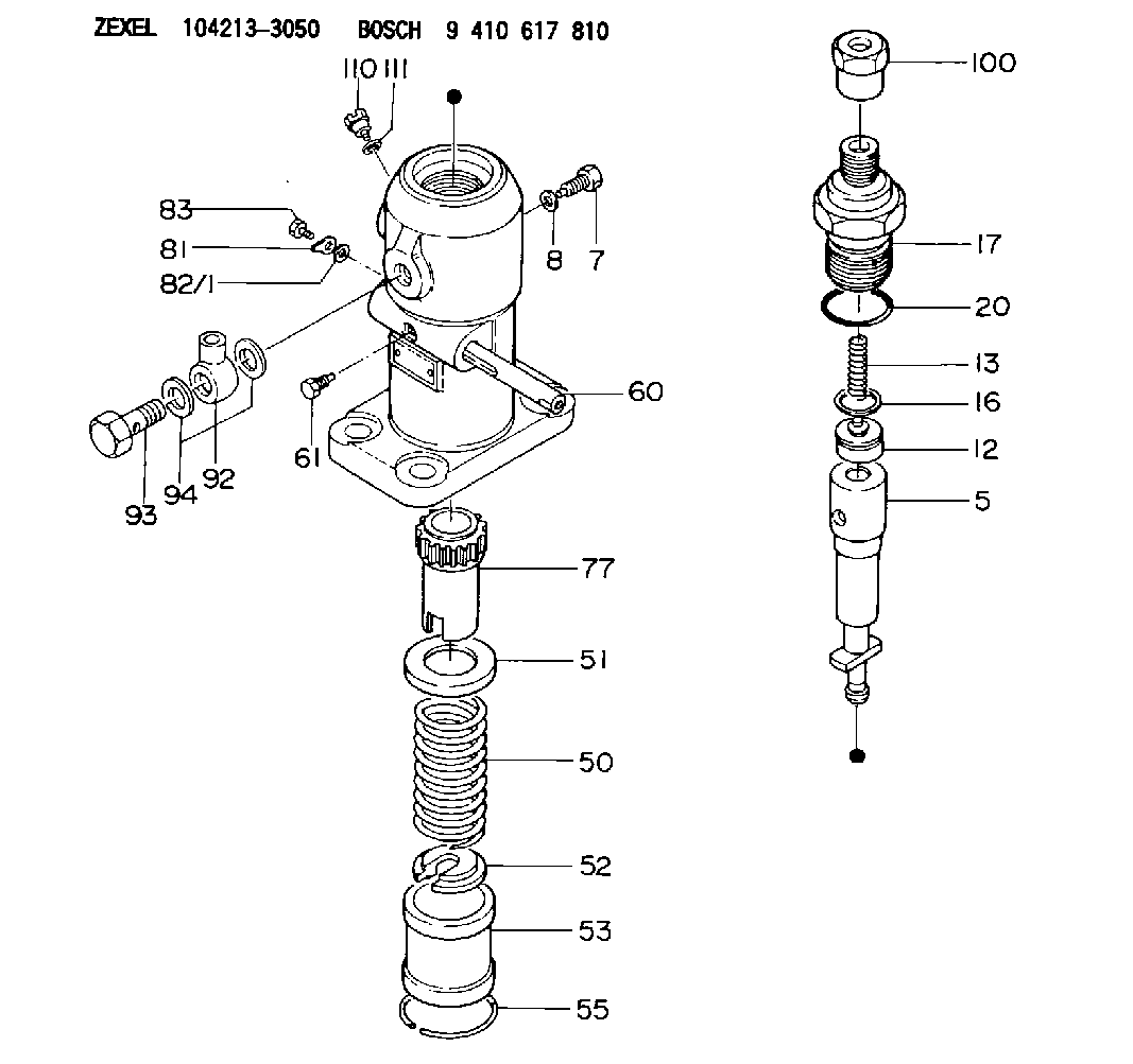
| 5. | [1] | 141171-0320 | PLUNGER-AND-BARREL ASSY |
| 7. | [1] | 141106-8300 | CAPSULE |
| 8. | [1] | 029331-2130 | GASKET |
| 12. | [1] | 141110-3020 | DELIVERY-VALVE ASSEMBLY |
| 13. | [1] | 141112-2000 | COMPRESSION SPRING |
| 16. | [1] | 141115-4600 | GASKET |
| 17. | [1] | 141126-2620 | FITTING |
| 20. | [1] | 029635-0020 | O-RING |
| 50. | [1] | 141215-2601 | COMPRESSION SPRING |
| 51. | [1] | 141216-1800 | SLOTTED WASHER |
| 52. | [1] | 141217-3000 | SLOTTED WASHER |
| 53. | [1] | 141218-5020 | GUIDE |
| 55. | [1] | 141220-1200 | LOCKING WASHER |
| 60. | [1] | 141243-4000 | CONTROL RACK |
| 61. | [1] | 141226-3200 | BLEEDER SCREW |
| 77. | [1] | 141241-2700 | CONTROL SLEEVE |
| 81. | [1] | 141245-2000 | POINTER |
| 82/1. | [0] | 023500-6210 | PLAIN WASHER D11&6.4T1.5 |
| 82/1. | [0] | 029300-6010 | PLAIN WASHER D11&6.4T0.8 |
| 82/1. | [0] | 029300-6020 | PLAIN WASHER D11&6.4T0.35 |
| 83. | [1] | 020006-1440 | BLEEDER SCREW M6P1L14 |
| 92. | [1] | 029702-6020 | INLET UNION |
| 93. | [1] | 029732-6010 | EYE BOLT |
| 94. | [2] | 026526-3440 | GASKET |
| 100. | [1] | 029762-6140 | UNION NUT |
| 110. | [1] | 141420-1600 | BLEEDER SCREW |
| 111. | [1] | 026506-1040 | GASKET D9.9&6.2T1 |
Cross reference number
Zexel num
Bosch num
Firm num
Name
104213-3050
FUEL-INJECTION PUMP
K 24FA FUEL INJECTION PUMP PF-1GD(V) PF
K 24FA FUEL INJECTION PUMP PF-1GD(V) PF
Information:
13. Install spring (16), bellcrank (17), and retaining ring (15) on cover assembly (14). 14. Install gasket (24) bellcrank assembly (14) and two bolts (13) on timing advance housing. 15. Install timing advance housing (11) on the timing gear cover. Remove the screwdriver. 16. Check the position (protrusion) of ball detent (25) in tool (B). It should protrude only slightly into the grooved area. During the following steps, tool (B) and the area of installation cannot be seen. The cutaway views are shown for better photo illustration. 17. Install tool (B) with grooved side toward the engine, between the power piston bearing and bellcrank (17) so that ear (26) is in an approximate 9 o'clock position. 18. Apply a slight hand pressure and push tool (B) towards the engine and rotate counterclockwise slowly until ear (27) is in an approximately 9 o'clock position. A slight resistance as the tool starts to seat can be felt.19. Continue to rotate tool (B) counterclockwise until ear (27) is in an approximate 6 o'clock position. 20. Carefully install timing position sensor (6), spring (28), damping washer (29), bracket (8), collar (10) and locknut (9). Do not tighten locknut (9) at this time.21. Connect the wiring harness from the timing position sensor to the wiring harness on the engine. (J2/P2 connector). Be sure that the harness from the PEEC control module is connected to the engine wiring harness. (J7/P7 connector)22. Disconnect the PEEC data link connector (the short pigtail out of the top of the PEEC control module - J4/P4 connector) from the truck wiring harness and connect either tool (C) or tool (D) to the PEEC data link connector (J8 connector).23. Turn power on the PEEC control module. Select "Timing Position Sensor Calibration" from the main menu of tool (C) or (D). See Special Instructions, Form No's. SEHS8742 and/or SEHS8743.
Do not engage the starter, or damage to the engine will be the result.
24. Adjust collar (10) on timing position sensor until the bar graph on tool (C) or (D) is centered and indicate the timing position sensor is calibrated.25. Tighten locknut (9) to 55 7 N m (41 5 lb.ft.).26. Check the timing position calibration reading on tool (C) or (D) to insure that the timing position sensor is still in calibration after tightening the locknut.27. Turn off power to the PEEC control module.28. Disconnect tool (C) or (D) from the PEEC control module. Connect the PEEC data link connector (J1 connector) to the truck harness (P1 connector).29. Remove tool (B) from between the power piston and the bellcrank.30. Use tool (E) to rotate the engine in the clockwise direction to release the pressure on tool (F). Remove tool (F). 31. Lubricate o-ring seal (31) with engine oil and install on timing solenoid (5).32. Install timing solenoid (5) into the timing advance housing. Be sure lever (32) is engaged in the groove of the sleeve. Access port (33) has been provided to visually check the position of lever (32). 33.