Information fuel-injection pump
BOSCH
F 01G 09Y 022
f01g09y022
ZEXEL
104206-4080
1042064080
KUBOTA
1G678-51012
1g67851012

Rating:
Compare Prices: .
As an associate, we earn commssions on qualifying purchases through the links below

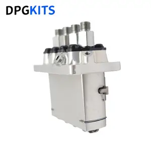
Original Fuel Injection Pump Compatible With Kubota V1505 1G678-51012 104206-4080 F01G09Y022 Excavator Engine Replacement Parts
YERCBX The key components have excellent wear resistance, extending the overall service life || Integrated design: Compact structure, small space occupation, and convenient for vehicle installation and layout. || Easy maintenance: The design is reasonable, and daily inspection and maintenance operations are simple, saving time || Lightweight design: Reducing its own weight helps to achieve overall lightweighting of the vehicle || The installation interface design is convenient for installation and saves installation time.
YERCBX The key components have excellent wear resistance, extending the overall service life || Integrated design: Compact structure, small space occupation, and convenient for vehicle installation and layout. || Easy maintenance: The design is reasonable, and daily inspection and maintenance operations are simple, saving time || Lightweight design: Reducing its own weight helps to achieve overall lightweighting of the vehicle || The installation interface design is convenient for installation and saves installation time.

You can express buy:
USD 825.02
14-06-2025
14-06-2025
New Fuel Pump 1G678-51012 104206-4080 F01G09Y022 For Kubota V1505 Engine
Images:
USD 643.94

[14-Jun-2025]
Components :
| 0. | INJECTION-PUMP ASSEMBLY | 104206-4080 |
| 1. | _ | |
| 2. | FUEL INJECTION PUMP | |
| 3. | NUMBER PLATE | |
| 4. | _ | |
| 5. | CAPSULE | |
| 6. | ADJUSTING DEVICE | |
| 7. | NOZZLE AND HOLDER ASSY | |
| 8. | Nozzle and Holder | |
| 9. | Open Pre:MPa(Kqf/cm2) | |
| 10. | NOZZLE-HOLDER | |
| 11. | NOZZLE |
Scheme ###:
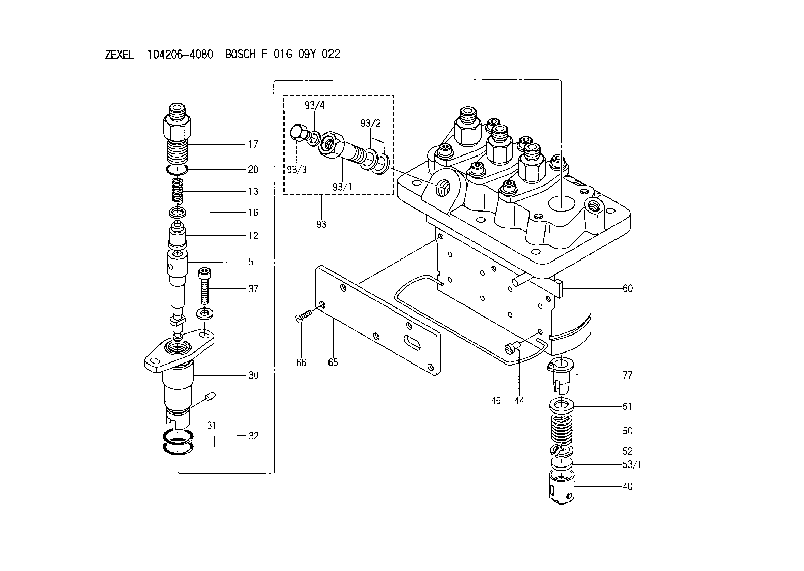
| 5. | [4] | 140161-0720 | PLUNGER-AND-BARREL ASSY M36 |
| 12. | [4] | 140110-4420 | DELIVERY-VALVE ASSEMBLY K25 |
| 13. | [4] | 140112-2800 | COMPRESSION SPRING |
| 16. | [4] | 140115-2200 | GASKET |
| 17. | [4] | 140116-7220 | FITTING |
| 20. | [4] | 140118-0500 | O-RING |
| 30. | [4] | 140131-0021 | FLANGE BUSHING |
| 31. | [4] | 140271-0000 | BEARING PIN |
| 32. | [8] | 140118-0400 | O-RING |
| 37. | [8] | 140124-0100 | FLAT-HEAD SCREW |
| 40. | [4] | 140200-2320 | TAPPET |
| 44. | [4] | 140212-0300 | BEARING PIN |
| 45. | [1] | 140213-1200 | LOCKING WASHER |
| 50. | [4] | 140215-2000 | COMPRESSION SPRING |
| 51. | [4] | 140216-1300 | SLOTTED WASHER |
| 52. | [4] | 140254-2900 | SLOTTED WASHER |
| 53/1. | [1] | 140254-1400 | PLATE T1.80 |
| 53/1. | [1] | 140254-1500 | PLATE T1.85 |
| 53/1. | [1] | 140254-1600 | PLATE T1.90 |
| 53/1. | [1] | 140254-1700 | PLATE T1.95 |
| 53/1. | [1] | 140254-1800 | PLATE T2.00 |
| 53/1. | [1] | 140254-1900 | PLATE T2.05 |
| 53/1. | [1] | 140254-2000 | PLATE T2.10 |
| 53/1. | [1] | 140254-2100 | PLATE T2.15 |
| 53/1. | [1] | 140254-2200 | PLATE T2.20 |
| 53/1. | [1] | 140254-2300 | PLATE T2.25 |
| 53/1. | [1] | 140254-2400 | PLATE T2.30 |
| 53/1. | [1] | 140254-2500 | PLATE T2.35 |
| 53/1. | [1] | 140254-2600 | PLATE T2.40 |
| 53/1. | [1] | 140254-2700 | PLATE T2.45 |
| 53/1. | [1] | 140254-2800 | PLATE T2.50 |
| 53/1. | [1] | 140254-3100 | PLATE T1.825 |
| 53/1. | [1] | 140254-3200 | PLATE T1.875 |
| 53/1. | [1] | 140254-3300 | PLATE T1.925 |
| 53/1. | [1] | 140254-3400 | PLATE T1.975 |
| 53/1. | [1] | 140254-3500 | PLATE T2.025 |
| 53/1. | [1] | 140254-3600 | PLATE T2.075 |
| 53/1. | [1] | 140254-3700 | PLATE T2.125 |
| 53/1. | [1] | 140254-3800 | PLATE T2.175 |
| 53/1. | [1] | 140254-3900 | PLATE T2.225 |
| 53/1. | [1] | 140254-4000 | PLATE T2.275 |
| 53/1. | [1] | 140254-4100 | PLATE T2.325 |
| 53/1. | [1] | 140254-4200 | PLATE T2.375 |
| 53/1. | [1] | 140254-4300 | PLATE T2.425 |
| 53/1. | [1] | 140254-4400 | PLATE T2.475 |
| 53/1. | [1] | 140254-4500 | PLATE T2.525 |
| 60. | [1] | 140243-6920 | CONTROL ROD |
| 65. | [1] | 140262-1301 | PLATE |
| 66. | [5] | 140252-0001 | FLAT-HEAD SCREW |
| 77. | [4] | 140241-4021 | CONTROL SLEEVE |
| 93. | [1] | 140402-3620 | EYE BOLT |
| 93/1. | [1] | 140402-3500 | EYE BOLT |
| 93/2. | [2] | 026510-1340 | GASKET |
| 93/3. | [1] | 140420-2400 | BLEEDER SCREW |
| 93/4. | [1] | 026506-1040 | GASKET |
Cross reference number
Zexel num
Bosch num
Firm num
Name
Information:
(1) End play for shaft (new) ... 0.102 0.025 mm (.004 .001 in) Maximum permissible end play (worn) ... 0.20 mm (.008 in)(2) Thickness of thrust bearing (where thrust rings contact bearing) ... 5.36 0.03 mm (.211 .001 in)(3) Diameter of shaft (new) ... 12.697 to 12.705 mm (.4999 to .5002 in) Bore in the bearing (new) ... 12.741 to 12.748 mm (.5016 to .5019 in)Maximum permissible clearance between bearing and shaft (worn) ... 0.05 mm (.002 in)(4) Maximum permissible gap of oil seal ring, measured in bore of housing ... 0.25 mm (.010 in)(5) Install the compressor wheel (at room temperature) as follows: a. Put compressor wheel on the shaft.b. Put a small amount of clean engine oil on the threads.c. Tighten the nut to 14 to 17 N m (125 to 150 lb in).d. Remove nut from shaft and apply 6V1541 Quick Cure Primer on the threads of the shaft and nut followed by application of 9S3263 Retaining Compound.e. Tighten nut to a torque of ... 24 2 N m (216 12 lb in)(6) Thickness of each thrust ring ... 2.553 0.013 mm (.1005 .0005 in)(7) Bore in housing (new) ... 20.744 to 20.757 mm (.8167 to .8172 in) Outside diameter of the bearing (new) ... 20.630 to 20.643 mm (.8122 to .8127 in)Maximum permissible clearance between bearing and bore in housing (worn) ... 0.15 mm (.006 in)Torque for four nuts (put 5P3931 Anti-Seize Compound on threads) and bolts that hold turbocharger to exhaust manifold ... 55 5 N m (40 4 lb ft)Install the band clamps to hold the cartridge to the compressor housing as follows: a. Tighten clamps to ... 14 1.1 N m (125 10 lb in)b. Tap (hit) clamp lightly all around.c. Tighten again to ... 14 1.1 N m (125 10 lb in) Put clean engine oil in the oil inlet of the turbocharger after assembly or before installation to provide start up lubrication and/or storage protection.Schwitzer S2BG
(1) Clearance between ends of oil seal ring (when installed in bore) ... 0.05 to 0.25 mm (.002 to .010 in)(2) Apply 5P3931 Anti-Seize Compound to threads of bolts that hold turbine housing to turbocharger. Tighten to a torque of ... 15.8 0.5 N m (140 5 lb in)(3) Tighten bolts that hold compressor housing to turbocharger cartridge to a torque of ... 7.3 0.5 N m (65 5 lb in)(4) Compressor wheel installation: a. Install wheel on shaft.b. Put 1 drop of 7M7456 Bearing Mount on shaft threads.c. Tighten nut to a torque of ... 10.2 0.5 N m (90 5 lb in)(5) End play for shaft ... 0.051 to 0.083 mm (.0020 to .0033 in)(6) Apply 5P3931 Anti-Seize Compound. Tighten to a torque of ... 54 5 N m (40 4 lb ft)(7) Bore in housing for bearings ... 17.991
(1) Clearance between ends of oil seal ring (when installed in bore) ... 0.05 to 0.25 mm (.002 to .010 in)(2) Apply 5P3931 Anti-Seize Compound to threads of bolts that hold turbine housing to turbocharger. Tighten to a torque of ... 15.8 0.5 N m (140 5 lb in)(3) Tighten bolts that hold compressor housing to turbocharger cartridge to a torque of ... 7.3 0.5 N m (65 5 lb in)(4) Compressor wheel installation: a. Install wheel on shaft.b. Put 1 drop of 7M7456 Bearing Mount on shaft threads.c. Tighten nut to a torque of ... 10.2 0.5 N m (90 5 lb in)(5) End play for shaft ... 0.051 to 0.083 mm (.0020 to .0033 in)(6) Apply 5P3931 Anti-Seize Compound. Tighten to a torque of ... 54 5 N m (40 4 lb ft)(7) Bore in housing for bearings ... 17.991