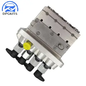
Information fuel-injection pump
BOSCH
9 410 617 339
9410617339
ZEXEL
104206-4040
1042064040
KUBOTA
1669551012
1669551012

Rating:
Compare Prices: .
As an associate, we earn commssions on qualifying purchases through the links below

Fuel Injection Pump Excavator Engine Replacement Parts.Compatible For Kubota V1505 16695-51012 104206-4040 9410617339
WWEIMNS OEM : 16695-51012 104206-4040 9410617339 || Adaptability: Fuel pumps have a wide range of adaptability and can be applied to different types of engines and fuel systems, meeting needs of various vehicles and providing better performance and driving experience. || Safety: fuel pump is equipped with various safety devices and protection mechanisms, such as overvoltage protection, overcurrent protection, etc., to ensure timely cut-off of fuel supply in abnormal situations and protect safety of vehicle and passengers. || Kind reminder: Before purchasing, please confirm that your shipping address is correct and that product and model you ordered are correct. After confirming that there are no errors, you can rest assured to purchase. If you have any questions, please send an email and our professional staff will solve them for you! || Team Objective: Our team has launched thousands of alternative products to provide customers with complete and efficient solutions. Providing customers with car components ha
WWEIMNS OEM : 16695-51012 104206-4040 9410617339 || Adaptability: Fuel pumps have a wide range of adaptability and can be applied to different types of engines and fuel systems, meeting needs of various vehicles and providing better performance and driving experience. || Safety: fuel pump is equipped with various safety devices and protection mechanisms, such as overvoltage protection, overcurrent protection, etc., to ensure timely cut-off of fuel supply in abnormal situations and protect safety of vehicle and passengers. || Kind reminder: Before purchasing, please confirm that your shipping address is correct and that product and model you ordered are correct. After confirming that there are no errors, you can rest assured to purchase. If you have any questions, please send an email and our professional staff will solve them for you! || Team Objective: Our team has launched thousands of alternative products to provide customers with complete and efficient solutions. Providing customers with car components ha

$737.68
20 Dec 2024
CN: GSHLGAO Flagship sto
New Fuel Injection Pump Fits for Kubota V1505 Engine 9410617339 104206-4040 16695-51012
GSHLGAO Part Name: Fuel Injection Pump || Part Number:1669551012 1042064040 16695-51012 104206-4040 9410617339 || Application: Compatible with the Kubota V1505 engine, this product is designed to seamlessly integrate and provide optimal performance. || Notification-The application information provided is for guidance purposes only. It is recommended to verify the part number and conduct a comparison with the old parts before making a purchase. Should you have any inquiries, please do not hesitate to contact us. || Premium Selection-This item boasts consistent performance, exceptional reliability, effortless installation, and rapid response times.
GSHLGAO Part Name: Fuel Injection Pump || Part Number:1669551012 1042064040 16695-51012 104206-4040 9410617339 || Application: Compatible with the Kubota V1505 engine, this product is designed to seamlessly integrate and provide optimal performance. || Notification-The application information provided is for guidance purposes only. It is recommended to verify the part number and conduct a comparison with the old parts before making a purchase. Should you have any inquiries, please do not hesitate to contact us. || Premium Selection-This item boasts consistent performance, exceptional reliability, effortless installation, and rapid response times.
You can express buy:
USD 742.07
19-06-2025
19-06-2025
1pc Fuel Pump 16695-51012 104206-4040 9410617339 For Kubota V1505 Engine Excavator Parts 3 Month Warranty Fuel Supply System
Images:
USD 420.9

[26-Jun-2025]
Components :
| 0. | INJECTION-PUMP ASSEMBLY | 104206-4040 |
| 1. | _ | |
| 2. | FUEL INJECTION PUMP | |
| 3. | NUMBER PLATE | |
| 4. | _ | |
| 5. | CAPSULE | |
| 6. | ADJUSTING DEVICE | |
| 7. | NOZZLE AND HOLDER ASSY | 105148-1350 |
| 8. | Nozzle and Holder | |
| 9. | Open Pre:MPa(Kqf/cm2) | 13.2{135} |
| 10. | NOZZLE-HOLDER | 105078-0200 |
| 11. | NOZZLE | 105007-1330 |
Scheme ###:
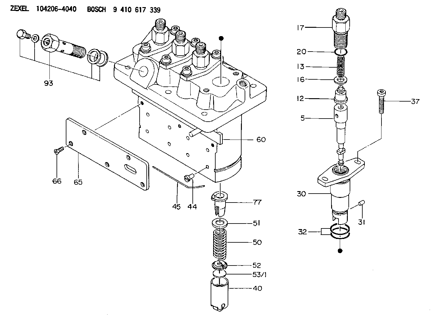
| 5. | [4] | 140154-9420 | PLUNGER-AND-BARREL ASSY |
| 12. | [4] | 140110-4420 | DELIVERY-VALVE ASSEMBLY |
| 13. | [4] | 140112-2800 | COMPRESSION SPRING |
| 16. | [4] | 140115-2200 | GASKET D12.8&8.6T0.5 |
| 17. | [4] | 140116-7220 | FITTING |
| 20. | [4] | 016550-1220 | O-RING |
| 30. | [4] | 140131-0021 | FLANGE BUSHING |
| 31. | [4] | 140271-0000 | BEARING PIN |
| 32. | [8] | 016550-1620 | O-RING |
| 37. | [8] | 140124-0100 | FLAT-HEAD SCREW |
| 40. | [4] | 140200-2320 | TAPPET |
| 44. | [4] | 140212-0300 | BEARING PIN |
| 45. | [1] | 140213-1200 | LOCKING WASHER |
| 50. | [4] | 140215-2000 | COMPRESSION SPRING |
| 51. | [4] | 140216-1300 | SLOTTED WASHER |
| 52. | [4] | 140254-2900 | SLOTTED WASHER |
| 53/1. | [1] | 140254-1400 | PLATE T1.80 |
| 53/1. | [1] | 140254-1500 | PLATE T1.85 |
| 53/1. | [1] | 140254-1600 | PLATE T1.90 |
| 53/1. | [1] | 140254-1700 | PLATE T1.95 |
| 53/1. | [1] | 140254-1800 | PLATE T2.00 |
| 53/1. | [1] | 140254-1900 | PLATE T2.05 |
| 53/1. | [1] | 140254-2000 | PLATE T2.10 |
| 53/1. | [1] | 140254-2100 | PLATE T2.15 |
| 53/1. | [1] | 140254-2200 | PLATE T2.20 |
| 53/1. | [1] | 140254-2300 | PLATE T2.25 |
| 53/1. | [1] | 140254-2400 | PLATE T2.30 |
| 53/1. | [1] | 140254-2500 | PLATE T2.35 |
| 53/1. | [1] | 140254-2600 | PLATE T2.40 |
| 53/1. | [1] | 140254-2700 | PLATE T2.45 |
| 53/1. | [1] | 140254-2800 | PLATE T2.50 |
| 53/1. | [1] | 140254-3100 | PLATE T1.825 |
| 53/1. | [1] | 140254-3200 | PLATE T1.875 |
| 53/1. | [1] | 140254-3300 | PLATE T1.925 |
| 53/1. | [1] | 140254-3400 | PLATE T1.975 |
| 53/1. | [1] | 140254-3500 | PLATE T2.025 |
| 53/1. | [1] | 140254-3600 | PLATE T2.075 |
| 53/1. | [1] | 140254-3700 | PLATE T2.125 |
| 53/1. | [1] | 140254-3800 | PLATE T2.175 |
| 53/1. | [1] | 140254-3900 | PLATE T2.225 |
| 53/1. | [1] | 140254-4000 | PLATE T2.275 |
| 53/1. | [1] | 140254-4100 | PLATE T2.325 |
| 53/1. | [1] | 140254-4200 | PLATE T2.375 |
| 53/1. | [1] | 140254-4300 | PLATE T2.425 |
| 53/1. | [1] | 140254-4400 | PLATE T2.475 |
| 53/1. | [1] | 140254-4500 | PLATE T2.525 |
| 60. | [1] | 140243-6920 | CONTROL ROD |
| 65. | [1] | 140262-1300 | PLATE |
| 66. | [5] | 140252-0000 | FLAT-HEAD SCREW |
| 77. | [4] | 140241-4021 | CONTROL SLEEVE |
| 93. | [1] | 140402-3222 | EYE BOLT |
Cross reference number
Zexel num
Bosch num
Firm num
Name
Information:
1. Disconnect plug P14 from receptacle J14. The locking ring helps identify P14 from J14. Check the connections for damaged wires or pins and corrosion. Also check that the pins are at the proper height in the connector. Check that the wires and pins are tight in the connectors by pulling (slightly) on each wire of each connector (including the breakout "T").2. Install 8T8694 Adapter (five pin breakout "T") between J14 and P14. Twist the locking rings to secure the connections.3. Connect the voltmeter as shown. Check for the appropriate voltages between the lettered "T" pins as explained in Steps 4 through 7.4. Pin A (+) to pin B (ground) system voltage should be approximately 12 volts DC with key on (no accessories). Minimum voltage is 11.0 volts DC. Diagnosis - Using the truck wiring schematic, check wires A and B and connections from J14 through the truck wiring harness back to the battery for proper voltage.5. If the voltage check between pins A and B is less than 11.0 volts with the key on, check the voltage drop from pin B to the negative battery post while cranking. For this test, the common lead (black) should be connected to the negative battery post first. Then place the positive (red) lead into pin B. (Pin B is chassis ground.) Voltage should be less than .5 volts DC when cranking. Diagnosis - If the voltage drop is greater than .5 volts DC, check wire B and connections (including the battery post connections) from J14 to battery negative. Follow the truck wiring schematic to trace the electrical path from J14 to chassis ground. Step 6 checks the proper functioning of the truck wiring, vehicle speed sensor and vehicle speed buffer. If proper vehicle speed is present on the appropriate status screens of the 3176 (7X1055) DDT or the (8T8697) ECAP service tools during road test than Step 6 is not necessary.6. Pin C to pin B:* 0 volts when stopped.* Up to 2.3 volts DC with the transmission output shaft turning and the speedometer disconnected (open circuit).
Remove the axle shafts or disconnect the drive shaft from the transmission to perform this test. See the truck manufacturer's instructions for the correct procedure(s).
Diagnosis: Remove magnetic pickup (vehicle speed sensor) from transmission. If pickup has collected significant metal debris, wipe it clean. Check the magnetic pickup per the manufactures specifications. Install a properly functioning magnetic pickup to the proper depth and reconnect to the vehicle speed buffer. Repeat Step 6. The problem may reappear if transmission fluid is contaminated. Change transmission fluid if necessary.* Check wires and connectors for damage or corrosion from the magnetic pickup to vehicle speed buffer.* Replace vehicle speed buffer (Caterpillar supplied part).
Vehicle Speed Buffer (1) Magnetic Pickup (2) in transmission.7. Pin D to pin B (static check):* Disconnect the magnetic pickup (in transmission) from the input wires of the vehicle speed buffer. With the key on, the voltage should be 4.5-7.5 volts DC. Diagnosis - If the