Information fuel-injection pump
BOSCH
9 410 617 338
9410617338
ZEXEL
104206-4030
1042064030
KUBOTA
1605551011
1605551011

Rating:
Compare Prices: .
As an associate, we earn commssions on qualifying purchases through the links below

Aftermarket Fuel Injection Pump 16055-51011 9410617338 Fit Intended For Engine V1405
Generic Motorcycle Parts || Heavy Equipment Parts || Spare Parts || Fuel Systems
Generic Motorcycle Parts || Heavy Equipment Parts || Spare Parts || Fuel Systems

Fuel Injection Pump 16055-51011 9410617338 for Kubota Engine V1405
AUCALIWI Part number:16055-51011,9410617338 || Application:for Kubota Engine V1405
AUCALIWI Part number:16055-51011,9410617338 || Application:for Kubota Engine V1405

Components :
| 0. | INJECTION-PUMP ASSEMBLY | 104206-4030 |
| 1. | _ | |
| 2. | FUEL INJECTION PUMP | |
| 3. | NUMBER PLATE | |
| 4. | _ | |
| 5. | CAPSULE | |
| 6. | ADJUSTING DEVICE | |
| 7. | NOZZLE AND HOLDER ASSY | 105148-1350 |
| 8. | Nozzle and Holder | |
| 9. | Open Pre:MPa(Kqf/cm2) | 13.2{135} |
| 10. | NOZZLE-HOLDER | 105078-0200 |
| 11. | NOZZLE | 105007-1330 |
Scheme ###:
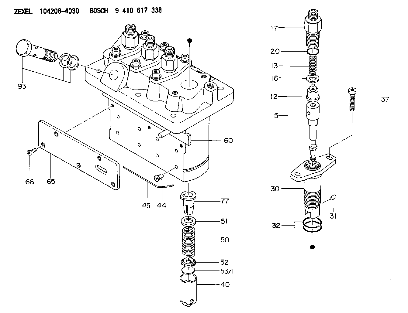
| 5. | [4] | 140154-9520 | PLUNGER-AND-BARREL ASSY |
| 12. | [4] | 140110-4420 | DELIVERY-VALVE ASSEMBLY |
| 13. | [4] | 140112-2800 | COMPRESSION SPRING |
| 16. | [4] | 140115-2200 | GASKET D12.8&8.6T0.5 |
| 17. | [4] | 140116-7220 | FITTING |
| 20. | [4] | 016550-1220 | O-RING |
| 30. | [4] | 140131-0021 | FLANGE BUSHING |
| 31. | [4] | 140271-0000 | BEARING PIN |
| 32. | [8] | 016550-1620 | O-RING |
| 37. | [8] | 140124-0100 | FLAT-HEAD SCREW |
| 40. | [4] | 140200-2320 | TAPPET |
| 44. | [4] | 140212-0300 | BEARING PIN |
| 45. | [1] | 140213-1200 | LOCKING WASHER |
| 50. | [4] | 140215-2000 | COMPRESSION SPRING |
| 51. | [4] | 140216-1300 | SLOTTED WASHER |
| 52. | [4] | 140254-2900 | SLOTTED WASHER |
| 53/1. | [1] | 140254-1400 | PLATE T1.80 |
| 53/1. | [1] | 140254-1500 | PLATE T1.85 |
| 53/1. | [1] | 140254-1600 | PLATE T1.90 |
| 53/1. | [1] | 140254-1700 | PLATE T1.95 |
| 53/1. | [1] | 140254-1800 | PLATE T2.00 |
| 53/1. | [1] | 140254-1900 | PLATE T2.05 |
| 53/1. | [1] | 140254-2000 | PLATE T2.10 |
| 53/1. | [1] | 140254-2100 | PLATE T2.15 |
| 53/1. | [1] | 140254-2200 | PLATE T2.20 |
| 53/1. | [1] | 140254-2300 | PLATE T2.25 |
| 53/1. | [1] | 140254-2400 | PLATE T2.30 |
| 53/1. | [1] | 140254-2500 | PLATE T2.35 |
| 53/1. | [1] | 140254-2600 | PLATE T2.40 |
| 53/1. | [1] | 140254-2700 | PLATE T2.45 |
| 53/1. | [1] | 140254-2800 | PLATE T2.50 |
| 53/1. | [1] | 140254-3100 | PLATE T1.825 |
| 53/1. | [1] | 140254-3200 | PLATE T1.875 |
| 53/1. | [1] | 140254-3300 | PLATE T1.925 |
| 53/1. | [1] | 140254-3400 | PLATE T1.975 |
| 53/1. | [1] | 140254-3500 | PLATE T2.025 |
| 53/1. | [1] | 140254-3600 | PLATE T2.075 |
| 53/1. | [1] | 140254-3700 | PLATE T2.125 |
| 53/1. | [1] | 140254-3800 | PLATE T2.175 |
| 53/1. | [1] | 140254-3900 | PLATE T2.225 |
| 53/1. | [1] | 140254-4000 | PLATE T2.275 |
| 53/1. | [1] | 140254-4100 | PLATE T2.325 |
| 53/1. | [1] | 140254-4200 | PLATE T2.375 |
| 53/1. | [1] | 140254-4300 | PLATE T2.425 |
| 53/1. | [1] | 140254-4400 | PLATE T2.475 |
| 53/1. | [1] | 140254-4500 | PLATE T2.525 |
| 60. | [1] | 140243-6920 | CONTROL ROD |
| 65. | [1] | 140262-1300 | PLATE |
| 66. | [5] | 140252-0000 | FLAT-HEAD SCREW |
| 77. | [4] | 140241-4021 | CONTROL SLEEVE |
| 93. | [1] | 140402-2921 | EYE BOLT |
Cross reference number
Zexel num
Bosch num
Firm num
Name
104206-4030
1605551011 KUBOTA
FUEL-INJECTION PUMP
K 23MD FUEL INJECTION PUMP PFR-4MD PFR
K 23MD FUEL INJECTION PUMP PFR-4MD PFR
104206-4030
1605551011 KUBOTA-EXTRA
FUEL-INJECTION PUMP
K 23MD FUEL INJECTION PUMP PFR-4MD PFR
K 23MD FUEL INJECTION PUMP PFR-4MD PFR
104206-4030
1605551011 KUBOTA
FUEL-INJECTION PUMP
K 23MD FUEL INJECTION PUMP PFR-4MD PFR
K 23MD FUEL INJECTION PUMP PFR-4MD PFR
Information:
1. Disconnect plug P11 from receptacle J11. The locking ring helps identify P11 from J11. Check the connections for damaged wires or pins and corrosion. Also check that the pins are at the proper height in the connector. Check that the wires and pins are tight in the connectors by pulling (slightly) on each wire of each connector (including the breakout "T").2. Install 8T8726 Adapter (three pin breakout "T") between J11 and P11. Twist the locking rings to secure the connections.3. Connect the voltmeter as shown. Check for the appropriate voltages between the lettered "T" pins as explained in Steps 4 through 6.4. Pin A (+) to pin B (ground) system voltage should be approximately 12 volts DC with key on (no accessories). Minimum voltage is 11.0 volts DC. While cranking, the voltage should be between 8-12 volts DC. Diagnosis - Using the truck wiring schematic, check wires A and B and connections from J11 through the truck wiring harness back to the battery terminals for proper voltage.5. If the voltage check between pins A and B is less than 11.0 volts with the key on, check the voltage drop from pin B to the negative battery post while cranking. For this test, the common lead (black) should be connected to the negative battery post first. Then place the positive (red) lead into pin B. (Pin B is chassis ground.) Voltage should be less than .5 volts DC when cranking. Diagnosis - If the voltage drop is greater than .5 volts DC, check wire B and connections (including the battery post connections) from J11 to battery negative. Follow the truck wiring schematic to trace the electrical path from J11 to chassis ground.6. Pin C to pin B:* Less than 1.0 volt DC with the key on and the foot pedal in the low idle position.* More than 3.5 volts DC with the foot pedal in the high idle position. Diagnosis - If pin A to pin B voltage is proper and the voltage from pin C to pin B does not vary from low idle to high idle, check J11 pin C and socket connection. Check for broken throttle linkage from foot pedal to throttle position sensor. (Throttle position sensor needs adjustment or replacement. See Electronic Troubleshooting, 3176 Diesel Truck Engine, Form No. SENR3913, or the Testing and Adjusting section in Systems Operation, Testing and Adjusting, 3176 Diesel Truck Engine, Form No. SENR3909. Caterpillar supplied part, but initial adjustment is OEM responsibility.)7. Disconnect breakout "T" and reconnect P11 to J11. Secure the locking ring.If problem has not been resolved, proceed to the next connector to be tested as shown in the Operational Problem Chart section.If this is the last connector to be checked for the operational problem being investigated:* The problem could lie within the customer specified parameters. Check with the 3176 (7X1055) DDT or the (8T8697) ECAP.* Check the throttle linkage for 100% throttle signal with the 3176 (7X1055) DDT or (8T8697) ECAP.* Review connector tests again.