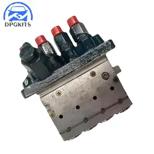
Information fuel-injection pump
BOSCH
9 410 617 337
9410617337
ZEXEL
104206-4020
1042064020
KUBOTA
1605451011
1605451011

Rating:
Compare Prices: .
As an associate, we earn commssions on qualifying purchases through the links below

YIHETOP Fuel Injection Pump Assembly 16054-51010 104206-4020 Compatible for Kubota Engine V1305 V1505
YIHETOP Replacement Part Number:16054-5101-0, 16054-51010, 1605451010, 16054-51011, 1605451011, 16054-5101-1, 104206-4020, 1042064020, 9410617337 || Compatible for Kubota Engine: V1305, V1505
YIHETOP Replacement Part Number:16054-5101-0, 16054-51010, 1605451010, 16054-51011, 1605451011, 16054-5101-1, 104206-4020, 1042064020, 9410617337 || Compatible for Kubota Engine: V1305, V1505

Original Fuel Injection Pump Compatible With Kubota V1505 16054-51011 104206-4020 9410617337 Excavator Engine Replacement Parts
YERCBX Enhance the engine's power output || Low-noise operation: Optimized internal structure and materials, resulting in low noise during operation || The key components have excellent wear resistance, extending the overall service life || Integrated design: Compact structure, small space occupation, and convenient for vehicle installation and layout. || Easy maintenance: The design is reasonable, and daily inspection and maintenance operations are simple, saving time
YERCBX Enhance the engine's power output || Low-noise operation: Optimized internal structure and materials, resulting in low noise during operation || The key components have excellent wear resistance, extending the overall service life || Integrated design: Compact structure, small space occupation, and convenient for vehicle installation and layout. || Easy maintenance: The design is reasonable, and daily inspection and maintenance operations are simple, saving time

You can express buy:
USD 742.07
01-05-2025
01-05-2025
1pc Fuel Pump 16054-51011 104206-4020 9410617337 For Kubota V1505 Engine Excavator Parts 3 Month Warranty Fuel Supply System
Components :
| 0. | INJECTION-PUMP ASSEMBLY | 104206-4020 |
| 1. | _ | |
| 2. | FUEL INJECTION PUMP | |
| 3. | NUMBER PLATE | |
| 4. | _ | |
| 5. | CAPSULE | |
| 6. | ADJUSTING DEVICE | |
| 7. | NOZZLE AND HOLDER ASSY | 105148-1350 |
| 8. | Nozzle and Holder | |
| 9. | Open Pre:MPa(Kqf/cm2) | 13.2{135} |
| 10. | NOZZLE-HOLDER | 105078-0200 |
| 11. | NOZZLE | 105007-1330 |
Scheme ###:
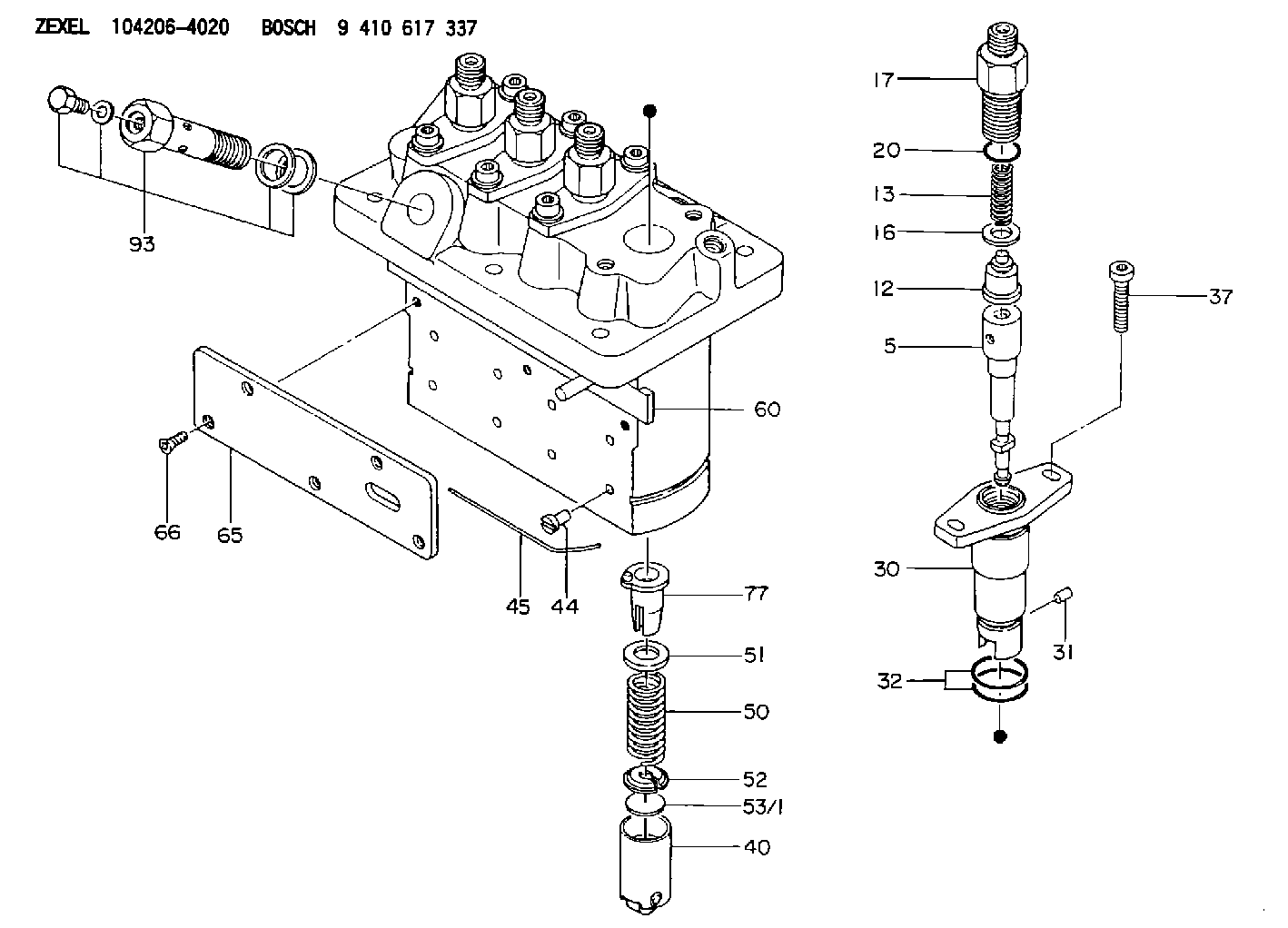
| 5. | [4] | 140154-9520 | PLUNGER-AND-BARREL ASSY |
| 12. | [4] | 140110-4420 | DELIVERY-VALVE ASSEMBLY |
| 13. | [4] | 140112-2800 | COMPRESSION SPRING |
| 16. | [4] | 140115-2200 | GASKET D12.8&8.6T0.5 |
| 17. | [4] | 140116-7220 | FITTING |
| 20. | [4] | 016550-1220 | O-RING |
| 30. | [4] | 140131-0021 | FLANGE BUSHING |
| 31. | [4] | 140271-0000 | BEARING PIN |
| 32. | [8] | 016550-1620 | O-RING |
| 37. | [8] | 140124-0100 | FLAT-HEAD SCREW |
| 40. | [4] | 140200-2320 | TAPPET |
| 44. | [4] | 140212-0300 | BEARING PIN |
| 45. | [1] | 140213-1200 | LOCKING WASHER |
| 50. | [4] | 140215-2000 | COMPRESSION SPRING |
| 51. | [4] | 140216-1300 | SLOTTED WASHER |
| 52. | [4] | 140254-2900 | SLOTTED WASHER |
| 53/1. | [1] | 140254-1400 | PLATE T1.80 |
| 53/1. | [1] | 140254-1500 | PLATE T1.85 |
| 53/1. | [1] | 140254-1600 | PLATE T1.90 |
| 53/1. | [1] | 140254-1700 | PLATE T1.95 |
| 53/1. | [1] | 140254-1800 | PLATE T2.00 |
| 53/1. | [1] | 140254-1900 | PLATE T2.05 |
| 53/1. | [1] | 140254-2000 | PLATE T2.10 |
| 53/1. | [1] | 140254-2100 | PLATE T2.15 |
| 53/1. | [1] | 140254-2200 | PLATE T2.20 |
| 53/1. | [1] | 140254-2300 | PLATE T2.25 |
| 53/1. | [1] | 140254-2400 | PLATE T2.30 |
| 53/1. | [1] | 140254-2500 | PLATE T2.35 |
| 53/1. | [1] | 140254-2600 | PLATE T2.40 |
| 53/1. | [1] | 140254-2700 | PLATE T2.45 |
| 53/1. | [1] | 140254-2800 | PLATE T2.50 |
| 53/1. | [1] | 140254-3100 | PLATE T1.825 |
| 53/1. | [1] | 140254-3200 | PLATE T1.875 |
| 53/1. | [1] | 140254-3300 | PLATE T1.925 |
| 53/1. | [1] | 140254-3400 | PLATE T1.975 |
| 53/1. | [1] | 140254-3500 | PLATE T2.025 |
| 53/1. | [1] | 140254-3600 | PLATE T2.075 |
| 53/1. | [1] | 140254-3700 | PLATE T2.125 |
| 53/1. | [1] | 140254-3800 | PLATE T2.175 |
| 53/1. | [1] | 140254-3900 | PLATE T2.225 |
| 53/1. | [1] | 140254-4000 | PLATE T2.275 |
| 53/1. | [1] | 140254-4100 | PLATE T2.325 |
| 53/1. | [1] | 140254-4200 | PLATE T2.375 |
| 53/1. | [1] | 140254-4300 | PLATE T2.425 |
| 53/1. | [1] | 140254-4400 | PLATE T2.475 |
| 53/1. | [1] | 140254-4500 | PLATE T2.525 |
| 60. | [1] | 140243-6920 | CONTROL ROD |
| 65. | [1] | 140262-1300 | PLATE |
| 66. | [5] | 140252-0000 | FLAT-HEAD SCREW |
| 77. | [4] | 140241-4021 | CONTROL SLEEVE |
| 93. | [1] | 140402-3620 | EYE BOLT |
Cross reference number
Zexel num
Bosch num
Firm num
Name
104206-4020
1605451011 KUBOTA
FUEL-INJECTION PUMP
K 23MD FUEL INJECTION PUMP PFR-4MD PFR
K 23MD FUEL INJECTION PUMP PFR-4MD PFR
104206-4020
1605451011 KUBOTA-EXTRA
FUEL-INJECTION PUMP
K 23MD FUEL INJECTION PUMP PFR-4MD PFR
K 23MD FUEL INJECTION PUMP PFR-4MD PFR
104206-4020
1605451011 KUBOTA
FUEL-INJECTION PUMP
K 23MD FUEL INJECTION PUMP PFR-4MD PFR
K 23MD FUEL INJECTION PUMP PFR-4MD PFR
Information:
1. Disconnect plug P7 from receptacle J7. The locking ring helps identify P7 from J7. Check the connections for damaged wires or pins and corrosion. Also check that the pins are at the proper height in the connector. Check that the wires and pins are tight in the connectors by pulling (slightly) on each wire of each connector (including the breakout "T").2. Install the 8T8695 Adapter (nine pin breakout "T") between J7 and P7. Twist the locking rings to secure the connections.3. Connect the voltmeter as shown. Check for the appropriate voltages between the lettered "T" pins as explained in Steps 4 through 11.4. Pin B (parking brake) to A (ground):* Less than .5 volts DC with the key on and parking brake applied.* More than 4.5 volts DC with the key on and parking brake released. Diagnosis - Disconnect breakout "T" and check the individual switch circuits for open, ground or faulty switch. Switch circuit must have less than 2.5 ohms resistance and more than 5000 ohms resistance to chassis ground.5. Pin C (brake switch) to A:* Less than .5 volts DC with the key on.* More than 4.5 volts DC with brake pedal applied and the key on. Diagnosis - Disconnect breakout "T" and check the individual switch circuits for open, ground or faulty switch. Switch circuit must have less than 2.5 ohms resistance and more than 5000 ohms resistance to chassis ground.
Vehicle Speed Buffer (1) Magnetic Pickup (2) in transmission. Step 6 checks the proper functioning of the truck wiring, vehicle speed sensor and vehicle speed buffer. If proper vehicle speed is present on the appropriate status screens of the 3176 (7X1055) DDT or the (8T8697) ECAP service tools during road test than Step 6 is not necessary.6. Pin D to pin A (static check): Disconnect the magnetic pickup (in transmission) from the input wires of the vehicle speed buffer.* Voltage should be 4.5 to 7.5 volts DC with the key on.
Vehicle Speed Buffer with Jumper Wire* With the jumper wire installed to the speed buffer input wires as shown, voltage is less than .75 volts DC with the key on. Diagnosis - If the voltages in both parts of Step 6 are correct, check the vehicle speed sensor per the manufactures specifications.In both parts of Step 6, if the voltage is 4.5 to 7.5 volts DC and does not change when the input wires are opened or jumpered: Remove breakout "T" and check wire from J7 pin D to J14 pin D for ground or open.* Remove the jumper wire and reconnect the magnetic pickup to vehicle speed buffer.7. Pin E to pin A:* Less than 1.0 volt DC with key on and foot pedal in low idle position.* More than 3.5 volts DC with foot pedal in high idle position. Diagnosis - Disconnect breakout "T". With the truck schematic, check wire E for continuity from J7 pin E to J11 pin C. Also check that wire E is not grounded to the