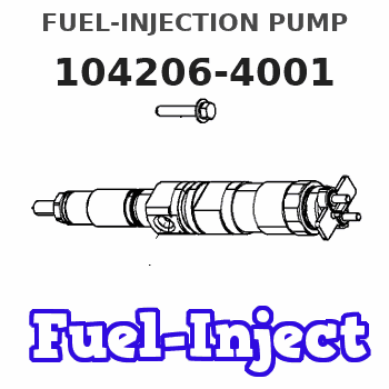
Information fuel-injection pump
BOSCH
9 410 617 122
9410617122
ZEXEL
104206-4001
1042064001
KUBOTA
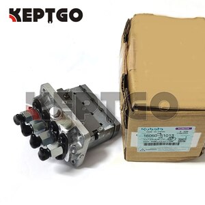
1606051012
1606051012
Rating:
Compare Prices: .
As an associate, we earn commssions on qualifying purchases through the links below

Engine Fuel Injection Pump, Compatible for Kubota V1305 V1505 16060-51012 104206-4001 9410617122 Excavator Replacement Parts
FDHABFN Part number: 16060-51012 104206-4001 9410617122 || Made of high-quality materials, with a sturdy structure and stable performance || The fuel injection pump is manufactured and tested to the strictest standards to ensure quality || Longer service life: High quality and durable materials, exquisite craftsmanship, and a series of tests conducted in the R&D center before launch provide reliable operation and longer service life || Why choose us: It is affordable, high-performance, durable, and designed with high-quality materials to improve reliability and durability. It has stable characteristics and high reliability. If the product you ordered malfunctions, damages, stops working, or has other issues, you can trust our worry free replacement or refund service.
FDHABFN Part number: 16060-51012 104206-4001 9410617122 || Made of high-quality materials, with a sturdy structure and stable performance || The fuel injection pump is manufactured and tested to the strictest standards to ensure quality || Longer service life: High quality and durable materials, exquisite craftsmanship, and a series of tests conducted in the R&D center before launch provide reliable operation and longer service life || Why choose us: It is affordable, high-performance, durable, and designed with high-quality materials to improve reliability and durability. It has stable characteristics and high reliability. If the product you ordered malfunctions, damages, stops working, or has other issues, you can trust our worry free replacement or refund service.

16060-51012 104206-4001 9410617122 New Fuel Injection Pump Fits for Kubota V1505 Engine
OSICAPEA ◆Part Name◆: Fuel Injection Pump || ◆Part Number◆:1606051012 1042064001 16060-51012 104206-4001 9410617122 || ◆Application◆: Fits for Kubota V1505 Engine || ◆Notice◆-Attention: If you are unsure if the product is suitable for your machine model. In order not to delay your use of the parts, please provide your engine nameplate or serial number and part number, and we will help you confirm if it is suitable. To avoid unnecessary returns, please carefully check the product image and part number to ensure that it is the product you want. Thank you for your support and understanding! || ◆Worth Choice◆-Tip: If you need any other parts, please contact us - we are a professional sales team and have many products to offer to you. Many buyers are very satisfied with our service. You can get first-class products and high-quality services from us, believe me, you will have a pleasant shopping experience here.
OSICAPEA ◆Part Name◆: Fuel Injection Pump || ◆Part Number◆:1606051012 1042064001 16060-51012 104206-4001 9410617122 || ◆Application◆: Fits for Kubota V1505 Engine || ◆Notice◆-Attention: If you are unsure if the product is suitable for your machine model. In order not to delay your use of the parts, please provide your engine nameplate or serial number and part number, and we will help you confirm if it is suitable. To avoid unnecessary returns, please carefully check the product image and part number to ensure that it is the product you want. Thank you for your support and understanding! || ◆Worth Choice◆-Tip: If you need any other parts, please contact us - we are a professional sales team and have many products to offer to you. Many buyers are very satisfied with our service. You can get first-class products and high-quality services from us, believe me, you will have a pleasant shopping experience here.
You can express buy:
USD 884
19-06-2023
19-06-2023
Original Brand New Fuel Injection Pump 16060-51012 For Kubota V1505 Engine 16060-51010 16060-51013
Components :
| 0. | INJECTION-PUMP ASSEMBLY | 104206-4001 |
| 1. | _ | |
| 2. | FUEL INJECTION PUMP | |
| 3. | NUMBER PLATE | |
| 4. | _ | |
| 5. | CAPSULE | |
| 6. | ADJUSTING DEVICE | |
| 7. | NOZZLE AND HOLDER ASSY | 105148-1350 |
| 8. | Nozzle and Holder | |
| 9. | Open Pre:MPa(Kqf/cm2) | 13.2{135} |
| 10. | NOZZLE-HOLDER | 105078-0200 |
| 11. | NOZZLE | 105007-1330 |
Scheme ###:
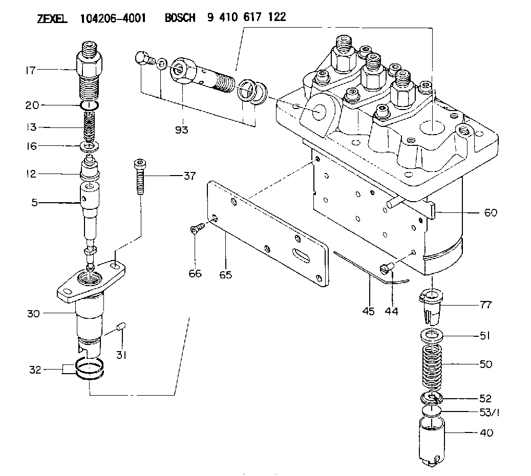
| 5. | [4] | 140161-0120 | PLUNGER-AND-BARREL ASSY |
| 12. | [4] | 140110-4420 | DELIVERY-VALVE ASSEMBLY |
| 13. | [4] | 140112-2800 | COMPRESSION SPRING |
| 16. | [4] | 140115-2200 | GASKET D12.8&8.6T0.5 |
| 17. | [4] | 140116-7220 | FITTING |
| 20. | [4] | 016550-1220 | O-RING |
| 30. | [4] | 140131-0021 | FLANGE BUSHING |
| 31. | [4] | 140271-0000 | BEARING PIN |
| 32. | [8] | 016550-1620 | O-RING |
| 37. | [8] | 140124-0100 | FLAT-HEAD SCREW |
| 40. | [4] | 140200-2320 | TAPPET |
| 44. | [4] | 140212-0300 | BEARING PIN |
| 45. | [1] | 140213-1200 | LOCKING WASHER |
| 50. | [4] | 140215-2000 | COMPRESSION SPRING |
| 51. | [4] | 140216-1300 | SLOTTED WASHER |
| 52. | [4] | 140254-2900 | SLOTTED WASHER |
| 53/1. | [1] | 140254-1400 | PLATE T1.80 |
| 53/1. | [1] | 140254-1500 | PLATE T1.85 |
| 53/1. | [1] | 140254-1600 | PLATE T1.90 |
| 53/1. | [1] | 140254-1700 | PLATE T1.95 |
| 53/1. | [1] | 140254-1800 | PLATE T2.00 |
| 53/1. | [1] | 140254-1900 | PLATE T2.05 |
| 53/1. | [1] | 140254-2000 | PLATE T2.10 |
| 53/1. | [1] | 140254-2100 | PLATE T2.15 |
| 53/1. | [1] | 140254-2200 | PLATE T2.20 |
| 53/1. | [1] | 140254-2300 | PLATE T2.25 |
| 53/1. | [1] | 140254-2400 | PLATE T2.30 |
| 53/1. | [1] | 140254-2500 | PLATE T2.35 |
| 53/1. | [1] | 140254-2600 | PLATE T2.40 |
| 53/1. | [1] | 140254-2700 | PLATE T2.45 |
| 53/1. | [1] | 140254-2800 | PLATE T2.50 |
| 53/1. | [1] | 140254-3100 | PLATE T1.825 |
| 53/1. | [1] | 140254-3200 | PLATE T1.875 |
| 53/1. | [1] | 140254-3300 | PLATE T1.925 |
| 53/1. | [1] | 140254-3400 | PLATE T1.975 |
| 53/1. | [1] | 140254-3500 | PLATE T2.025 |
| 53/1. | [1] | 140254-3600 | PLATE T2.075 |
| 53/1. | [1] | 140254-3700 | PLATE T2.125 |
| 53/1. | [1] | 140254-3800 | PLATE T2.175 |
| 53/1. | [1] | 140254-3900 | PLATE T2.225 |
| 53/1. | [1] | 140254-4000 | PLATE T2.275 |
| 53/1. | [1] | 140254-4100 | PLATE T2.325 |
| 53/1. | [1] | 140254-4200 | PLATE T2.375 |
| 53/1. | [1] | 140254-4300 | PLATE T2.425 |
| 53/1. | [1] | 140254-4400 | PLATE T2.475 |
| 53/1. | [1] | 140254-4500 | PLATE T2.525 |
| 60. | [1] | 140243-6920 | CONTROL ROD |
| 65. | [1] | 140262-1300 | PLATE |
| 66. | [5] | 140252-0000 | FLAT-HEAD SCREW |
| 77. | [4] | 140241-4021 | CONTROL SLEEVE |
| 93. | [1] | 140402-3620 | EYE BOLT |
Cross reference number
Zexel num
Bosch num
Firm num
Name
104206-4001
1606051012 KUBOTA
FUEL-INJECTION PUMP
K 23MD FUEL INJECTION PUMP PFR-4MD PFR
K 23MD FUEL INJECTION PUMP PFR-4MD PFR
Information:
Engine Runs Smoothly
Too Much Black Or Gray Exhaust Smoke 1. Poor Quality FuelIf poor or low quality fuel is suspected, use a source of known good quality fuel, and prime and start the engine. If the problem is resolved, drain the complete fuel system, replace the fuel filter, and add fuel recommended by Caterpillar.2. Fuel Injection Timing Out Of CalibrationCheck the fuel injection timing calibration and make necessary adjustments. See the topics, Engine Test Procedure Number P-402, [Checking Electronic Injection Timing With The Timing Adapter Tool Group And The ECAP (Electronic Control Analyzer and Programmer)], and Engine Test Procedure Number P-403, [Calibrating Electronic Injection Timing With The Timing Adapter Tool Group And The ECAP (Electronic Control Analyzer and Programmer)], in Electronic Troubleshooting, 3176 Diesel Truck Engine, Form No. SENR3913.3. Air Inlet Piping Damage Or RestrictionVisually inspect the air inlet system for damage or restriction. If leaks are found, repair or replace parts as required.If the air cleaner has an Air Cleaner Service Indicator, check the indicator for the position of the red piston. If the indicator shows red at any time, install a clean or new air cleaner element.Air inlet restriction can be checked with a water manometer or a vacuum gauge [measuring mm (inches) of water]. Make a connection to the piping between the air cleaner and the inlet to the turbocharger. The maximum restriction allowed, with the engine at full load rpm, is 635 mm (25 in) of water. If a water manometer or vacuum gauge is not available, visually check the air filter for dirt. Clean or replace as required.4. Exhaust System RestrictionVisually inspect the exhaust system for damage or restriction. If leaks are found, repair or replace parts as required.Exhaust system back pressure (pressure differential between the turbocharger exhaust outlet and atmosphere) should not exceed 1016 mm (40 in) of water. An alternative check would be to remove the exhaust piping, load the engine on a chassis dynamometer to determine if the problem is corrected. If this solves the problem, the restriction is in the muffler or truck piping.5. Valve Adjustment Not CorrectCheck and make any necessary adjustments. See the topic, Valve Clearance Setting, in 3176 Diesel Truck Engine Systems Operation And Testing and Adjusting, Form No. SENR3909. Intake valve clearance is 0.38 mm (.015 in), and exhaust valve clearance is 0.64 mm (.025 in).6. Defective Unit InjectorsA defective unit injector can be found, by running the engine at the rpm where the problem exists, with the use of the Electronic Control Analyzer and Programmer (ECAP) service tool Interactive Diagnostics feature (single cylinder cutout) to stop the fuel supply to each cylinder in turn. If a cylinder is found where the cutout makes no difference on the engine performance, that injector should be removed and tested. Drain the fuel supply manifold and remove the injector(s) (see 3176 Diesel Truck Engine Disassembly and Assembly, Form No. SENR3914).Testing of the injectors must be done off of the engine. Use the 1U6661 Pop (Injector) Tester Group with
Too Much Black Or Gray Exhaust Smoke 1. Poor Quality FuelIf poor or low quality fuel is suspected, use a source of known good quality fuel, and prime and start the engine. If the problem is resolved, drain the complete fuel system, replace the fuel filter, and add fuel recommended by Caterpillar.2. Fuel Injection Timing Out Of CalibrationCheck the fuel injection timing calibration and make necessary adjustments. See the topics, Engine Test Procedure Number P-402, [Checking Electronic Injection Timing With The Timing Adapter Tool Group And The ECAP (Electronic Control Analyzer and Programmer)], and Engine Test Procedure Number P-403, [Calibrating Electronic Injection Timing With The Timing Adapter Tool Group And The ECAP (Electronic Control Analyzer and Programmer)], in Electronic Troubleshooting, 3176 Diesel Truck Engine, Form No. SENR3913.3. Air Inlet Piping Damage Or RestrictionVisually inspect the air inlet system for damage or restriction. If leaks are found, repair or replace parts as required.If the air cleaner has an Air Cleaner Service Indicator, check the indicator for the position of the red piston. If the indicator shows red at any time, install a clean or new air cleaner element.Air inlet restriction can be checked with a water manometer or a vacuum gauge [measuring mm (inches) of water]. Make a connection to the piping between the air cleaner and the inlet to the turbocharger. The maximum restriction allowed, with the engine at full load rpm, is 635 mm (25 in) of water. If a water manometer or vacuum gauge is not available, visually check the air filter for dirt. Clean or replace as required.4. Exhaust System RestrictionVisually inspect the exhaust system for damage or restriction. If leaks are found, repair or replace parts as required.Exhaust system back pressure (pressure differential between the turbocharger exhaust outlet and atmosphere) should not exceed 1016 mm (40 in) of water. An alternative check would be to remove the exhaust piping, load the engine on a chassis dynamometer to determine if the problem is corrected. If this solves the problem, the restriction is in the muffler or truck piping.5. Valve Adjustment Not CorrectCheck and make any necessary adjustments. See the topic, Valve Clearance Setting, in 3176 Diesel Truck Engine Systems Operation And Testing and Adjusting, Form No. SENR3909. Intake valve clearance is 0.38 mm (.015 in), and exhaust valve clearance is 0.64 mm (.025 in).6. Defective Unit InjectorsA defective unit injector can be found, by running the engine at the rpm where the problem exists, with the use of the Electronic Control Analyzer and Programmer (ECAP) service tool Interactive Diagnostics feature (single cylinder cutout) to stop the fuel supply to each cylinder in turn. If a cylinder is found where the cutout makes no difference on the engine performance, that injector should be removed and tested. Drain the fuel supply manifold and remove the injector(s) (see 3176 Diesel Truck Engine Disassembly and Assembly, Form No. SENR3914).Testing of the injectors must be done off of the engine. Use the 1U6661 Pop (Injector) Tester Group with