Information fuel-injection pump
BOSCH
9 410 617 335
9410617335
ZEXEL
104206-4000
1042064000
KUBOTA
1606051011
1606051011

Rating:
Compare Prices: .
As an associate, we earn commssions on qualifying purchases through the links below

Fuel Injection Pump 16060-51010 16060-51013 16060-51011 for Kubota Engine V1505 V1505-E3B-AUSA-1 V1505T V1505-E2B-VERMEER-1 V1505-B Generator J116 J320
100% Apollo part number:16060-51010 16060-51013 16060-51011 || application: for Kubota Engine V1505 V1505-E3B-AUSA-1 V1505T V1505-E2B-VERMEER-1 V1505-B Generator J116 J320
100% Apollo part number:16060-51010 16060-51013 16060-51011 || application: for Kubota Engine V1505 V1505-E3B-AUSA-1 V1505T V1505-E2B-VERMEER-1 V1505-B Generator J116 J320

Fuel Injection Pump for Kubota V1505 V1505-B V1505T Engine J116 J320 J116-AUS J320-AUS Generator 16060-51010 16060-51011 16060-51013
KoovDem Part Number: 16060-51010 16060-51011 16060-51013 || Engine Model: for Kubota Engine V1505, V1505-E3B-AUSA-1, V1505T, V1505-E2B-VERMEER-1, V1505-B || Compatible with the following models of Kubota generators: J116, J320, J116-AUS, J320-AUS. || Effective and Reliable: Utilizing cutting-edge technology, this system delivers effective and reliable fuel supply, guaranteeing smooth vehicle performance. || Rugged and Dependable: With a track record of being rigorously tested and proven, this product offers durability and reliability, ensuring it operates consistently even in the harshest of environments.
KoovDem Part Number: 16060-51010 16060-51011 16060-51013 || Engine Model: for Kubota Engine V1505, V1505-E3B-AUSA-1, V1505T, V1505-E2B-VERMEER-1, V1505-B || Compatible with the following models of Kubota generators: J116, J320, J116-AUS, J320-AUS. || Effective and Reliable: Utilizing cutting-edge technology, this system delivers effective and reliable fuel supply, guaranteeing smooth vehicle performance. || Rugged and Dependable: With a track record of being rigorously tested and proven, this product offers durability and reliability, ensuring it operates consistently even in the harshest of environments.

16060-51010 16060-51011 16060-51013 Fuel Injection Pump for Kubota V1505 V1505-B V1505T Engine J116 J320 J116-AUS J320-AUS Generator
HIRINTOL 🔸Replace Part Number: 16060-51010 16060-51011 16060-51013 || 🔸Engine Model: for Kubota Engine V1505, V1505-E3B-AUSA-1, V1505T, V1505-E2B-VERMEER-1, V1505-B || 🔸Compatible Model: for Kubota Generator:J116, J320, J116-AUS, J320-AUS || 🔸Efficient And Stable: Using advanced technology, it can provide efficient and stable fuel supply to ensure the normal operation of the vehicle. || 🔸Durable And Reliable: Tested and proven many times, it has a long life and reliable quality to keep working under extreme conditions.
HIRINTOL 🔸Replace Part Number: 16060-51010 16060-51011 16060-51013 || 🔸Engine Model: for Kubota Engine V1505, V1505-E3B-AUSA-1, V1505T, V1505-E2B-VERMEER-1, V1505-B || 🔸Compatible Model: for Kubota Generator:J116, J320, J116-AUS, J320-AUS || 🔸Efficient And Stable: Using advanced technology, it can provide efficient and stable fuel supply to ensure the normal operation of the vehicle. || 🔸Durable And Reliable: Tested and proven many times, it has a long life and reliable quality to keep working under extreme conditions.
Components :
| 0. | INJECTION-PUMP ASSEMBLY | 104206-4000 |
| 1. | _ | |
| 2. | FUEL INJECTION PUMP | |
| 3. | NUMBER PLATE | |
| 4. | _ | |
| 5. | CAPSULE | |
| 6. | ADJUSTING DEVICE | |
| 7. | NOZZLE AND HOLDER ASSY | 105148-1350 |
| 8. | Nozzle and Holder | |
| 9. | Open Pre:MPa(Kqf/cm2) | 13.2{135} |
| 10. | NOZZLE-HOLDER | 105078-0200 |
| 11. | NOZZLE | 105007-1330 |
Scheme ###:
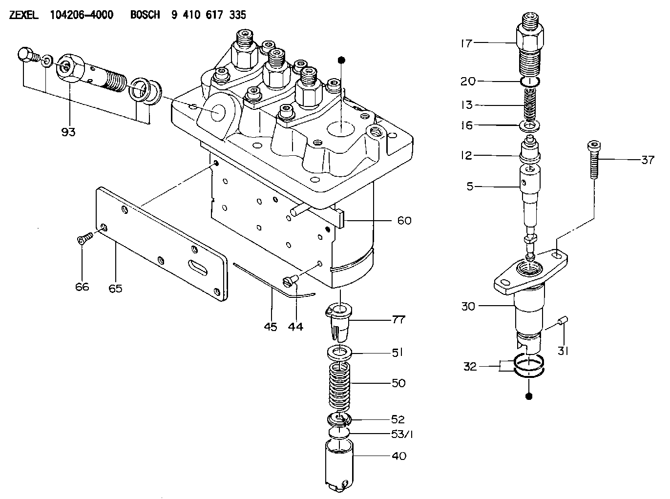
| 5. | [4] | 140154-9420 | PLUNGER-AND-BARREL ASSY |
| 12. | [4] | 140110-4420 | DELIVERY-VALVE ASSEMBLY |
| 13. | [4] | 140112-2800 | COMPRESSION SPRING |
| 16. | [4] | 140115-2200 | GASKET D12.8&8.6T0.5 |
| 17. | [4] | 140116-7220 | FITTING |
| 20. | [4] | 016550-1220 | O-RING |
| 30. | [4] | 140131-0021 | FLANGE BUSHING |
| 31. | [4] | 140271-0000 | BEARING PIN |
| 32. | [8] | 016550-1620 | O-RING |
| 37. | [8] | 140124-0100 | FLAT-HEAD SCREW |
| 40. | [4] | 140200-2320 | TAPPET |
| 44. | [4] | 140212-0300 | BEARING PIN |
| 45. | [1] | 140213-1200 | LOCKING WASHER |
| 50. | [4] | 140215-2000 | COMPRESSION SPRING |
| 51. | [4] | 140216-1300 | SLOTTED WASHER |
| 52. | [4] | 140254-2900 | SLOTTED WASHER |
| 53/1. | [1] | 140254-1400 | PLATE T1.80 |
| 53/1. | [1] | 140254-1500 | PLATE T1.85 |
| 53/1. | [1] | 140254-1600 | PLATE T1.90 |
| 53/1. | [1] | 140254-1700 | PLATE T1.95 |
| 53/1. | [1] | 140254-1800 | PLATE T2.00 |
| 53/1. | [1] | 140254-1900 | PLATE T2.05 |
| 53/1. | [1] | 140254-2000 | PLATE T2.10 |
| 53/1. | [1] | 140254-2100 | PLATE T2.15 |
| 53/1. | [1] | 140254-2200 | PLATE T2.20 |
| 53/1. | [1] | 140254-2300 | PLATE T2.25 |
| 53/1. | [1] | 140254-2400 | PLATE T2.30 |
| 53/1. | [1] | 140254-2500 | PLATE T2.35 |
| 53/1. | [1] | 140254-2600 | PLATE T2.40 |
| 53/1. | [1] | 140254-2700 | PLATE T2.45 |
| 53/1. | [1] | 140254-2800 | PLATE T2.50 |
| 53/1. | [1] | 140254-3100 | PLATE T1.825 |
| 53/1. | [1] | 140254-3200 | PLATE T1.875 |
| 53/1. | [1] | 140254-3300 | PLATE T1.925 |
| 53/1. | [1] | 140254-3400 | PLATE T1.975 |
| 53/1. | [1] | 140254-3500 | PLATE T2.025 |
| 53/1. | [1] | 140254-3600 | PLATE T2.075 |
| 53/1. | [1] | 140254-3700 | PLATE T2.125 |
| 53/1. | [1] | 140254-3800 | PLATE T2.175 |
| 53/1. | [1] | 140254-3900 | PLATE T2.225 |
| 53/1. | [1] | 140254-4000 | PLATE T2.275 |
| 53/1. | [1] | 140254-4100 | PLATE T2.325 |
| 53/1. | [1] | 140254-4200 | PLATE T2.375 |
| 53/1. | [1] | 140254-4300 | PLATE T2.425 |
| 53/1. | [1] | 140254-4400 | PLATE T2.475 |
| 53/1. | [1] | 140254-4500 | PLATE T2.525 |
| 60. | [1] | 140243-6920 | CONTROL ROD |
| 65. | [1] | 140262-1300 | PLATE |
| 66. | [5] | 140252-0000 | FLAT-HEAD SCREW |
| 77. | [4] | 140241-4021 | CONTROL SLEEVE |
| 93. | [1] | 140402-3620 | EYE BOLT |
Cross reference number
Zexel num
Bosch num
Firm num
Name
9 410 617 335
1606051011 KUBOTA-EXTRA
FUEL-INJECTION PUMP
* K 23MD PFR-4MD PFR
* K 23MD PFR-4MD PFR
Information:
Misfiring And Running Rough 1. Intermittent Electrical ConnectionLook at the "check engine" light on the dash to determine if there are any faults. See Electronic Troubleshooting, 3176 Diesel Truck Engine, Form No. SENR3913. If faults are found, follow the procedures to identify and correct the faults.2. Air In Fuel SystemDisconnect the fuel return line at the tank. Place this end of the line in a container of fuel to see if air bubbles are present while the engine is running. If air bubbles are observed, check for loose fittings or line leaks between the fuel tank and the fuel transfer pump. If leaks are found, tighten the connections or replace the line(s).To remove air from the engine fuel system: With the engine off, loosen the fuel return line fitting at the fuel manifold. Operate the fuel priming pump until the flow of fuel is free of air. Tighten the return line fitting, fasten the priming pump, and start the engine. If the engine still does not run smooth or produces a lot of white smoke, apply 35 kPa (5 psi) of air pressure to the fuel tank to force fuel through the system.
Do not use more than 55 kPa (8 psi) of air pressure in the fuel tank or damage to the tank may result.
Check the fuel return line for restriction. Replace if it is plugged.3. Poor Quality FuelIf poor or low quality fuel is suspected, use a source of known good quality fuel, prime and start the engine. If the problem is resolved, drain the complete fuel system, replace the fuel filter, and add fuel recommended by Caterpillar.4. Defective Unit InjectorsA defective unit injector can be found, by running the engine at the rpm where the problem exists, with the use of the Electronic Control Analyzer and Programmer (ECAP) service tool Interactive Diagnostics feature (single cylinder cutout) to stop the fuel supply to each cylinder in turn (see Electronic Troubleshooting, 3176 Diesel Truck Engine, Form No. SENR3913). If a cylinder is found where the cutout makes no difference on the engine performance, that injector should be removed and tested. Drain the fuel supply manifold and remove the injector(s) (see 3176 Diesel Truck Engine Disassembly and Assembly, Form No. SENR3914).Testing of the injectors must be done off of the engine. Use the 1U6661 Pop (Injector) Tester Group with a 1U6663 Injector Holding Block, and a 1U6665 Power Supply, to test the injectors. For the test procedure refer to Special Instruction, Form No. SEHS8867, Using The 1U6661 Pop (Injector) Tester. For test specifications refer to Special Instruction, Form No. SEHS8804, Unit Injector Test Specifications for 1.7 Liter Engines. Inspect and repair as necessary the sealing surface (seat) of the injector sleeve in the cylinder head when removing and installing an injector. The injector sealing surface (seat) must be free of scratches or evidence of combustion products. If it is necessary to rework (ream) or replace the sleeve use 4C4054 Tool Group and refer to Special Instruction, Form No. SEHS9120,