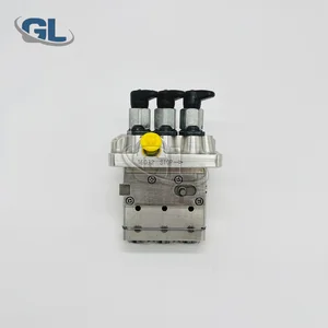
Information fuel-injection pump
BOSCH
9 410 617 333
9410617333
ZEXEL
104206-3020
1042063020
KUBOTA
1602951011
1602951011

Rating:
Compare Prices: .
As an associate, we earn commssions on qualifying purchases through the links below

Original Fuel Injection Pump Compatible With Kubota D722 Engine 16029-51011 104206-3020 9410617333 Excavator Engine Replacement Parts
YERCBX Easy installation: Reasonable design, easy to install and replace || Space optimization: Compact in size, it is convenient to install in the limited space of a vehicle || Easy to maintain: The structural design facilitates daily maintenance and upkeep || It can work normally under different conditions || Lightweight design: Utilizing lightweight materials to reduce the weight of the vehicle
YERCBX Easy installation: Reasonable design, easy to install and replace || Space optimization: Compact in size, it is convenient to install in the limited space of a vehicle || Easy to maintain: The structural design facilitates daily maintenance and upkeep || It can work normally under different conditions || Lightweight design: Utilizing lightweight materials to reduce the weight of the vehicle

WZCNLXLX NEW Fuel Pump 16029-51011 104206-3020 9410617333 For Kubota D722 Engine
WZCNLXLX Item Name:Fuel Injection Pump || Item Number:16029-51011 104206-3020 9410617333 || Application:For Kubota D722 Engine || Note: If you are unsure if the product is suitable.In order not to delay your use of the parts, please provide your engine nameplate or serial number and part number, and we will help you confirm if it is suitable. To avoid unnecessary returns, please check the product image and part number to ensure it is the product you want. || Tip: Please contact us - we are a professional sales team and we have many products to offer to you. Many buyers are very satisfied with our service. You can get first-class products and high-quality services from us, believe me, you will have a pleasant shopping experience here.
WZCNLXLX Item Name:Fuel Injection Pump || Item Number:16029-51011 104206-3020 9410617333 || Application:For Kubota D722 Engine || Note: If you are unsure if the product is suitable.In order not to delay your use of the parts, please provide your engine nameplate or serial number and part number, and we will help you confirm if it is suitable. To avoid unnecessary returns, please check the product image and part number to ensure it is the product you want. || Tip: Please contact us - we are a professional sales team and we have many products to offer to you. Many buyers are very satisfied with our service. You can get first-class products and high-quality services from us, believe me, you will have a pleasant shopping experience here.
You can express buy:
USD 350.75
26-06-2025
26-06-2025
China Made New Fuel Injection Pump 16029-51011 104206-3020 9410617333 compatible for Kubota D1105
Components :
| 0. | INJECTION-PUMP ASSEMBLY | 104206-3020 |
| 1. | _ | |
| 2. | FUEL INJECTION PUMP | |
| 3. | NUMBER PLATE | |
| 4. | _ | |
| 5. | CAPSULE | |
| 6. | ADJUSTING DEVICE | |
| 7. | NOZZLE AND HOLDER ASSY | 105148-1350 |
| 8. | Nozzle and Holder | |
| 9. | Open Pre:MPa(Kqf/cm2) | 13.2{135} |
| 10. | NOZZLE-HOLDER | 105078-0200 |
| 11. | NOZZLE | 105007-1330 |
Scheme ###:
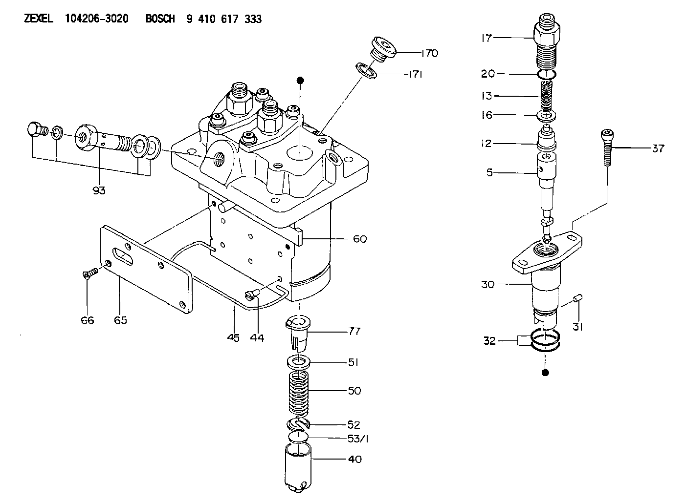
| 5. | [3] | 140154-9520 | PLUNGER-AND-BARREL ASSY |
| 12. | [3] | 140110-4420 | DELIVERY-VALVE ASSEMBLY |
| 13. | [3] | 140112-2800 | COMPRESSION SPRING |
| 16. | [3] | 140115-2200 | GASKET D12.8&8.6T0.5 |
| 17. | [3] | 140116-7220 | FITTING |
| 20. | [3] | 016550-1220 | O-RING |
| 30. | [3] | 140131-0021 | FLANGE BUSHING |
| 31. | [3] | 140271-0000 | BEARING PIN |
| 32. | [6] | 016550-1620 | O-RING |
| 37. | [6] | 140124-0100 | FLAT-HEAD SCREW |
| 40. | [3] | 140200-2320 | TAPPET |
| 44. | [3] | 140212-0300 | BEARING PIN |
| 45. | [1] | 140213-0900 | LOCKING WASHER |
| 50. | [3] | 140215-2000 | COMPRESSION SPRING |
| 51. | [3] | 140216-1300 | SLOTTED WASHER |
| 52. | [3] | 140254-2900 | SLOTTED WASHER |
| 53/1. | [1] | 140254-1400 | PLATE T1.80 |
| 53/1. | [1] | 140254-1500 | PLATE T1.85 |
| 53/1. | [1] | 140254-1600 | PLATE T1.90 |
| 53/1. | [1] | 140254-1700 | PLATE T1.95 |
| 53/1. | [1] | 140254-1800 | PLATE T2.00 |
| 53/1. | [1] | 140254-1900 | PLATE T2.05 |
| 53/1. | [1] | 140254-2000 | PLATE T2.10 |
| 53/1. | [1] | 140254-2100 | PLATE T2.15 |
| 53/1. | [1] | 140254-2200 | PLATE T2.20 |
| 53/1. | [1] | 140254-2300 | PLATE T2.25 |
| 53/1. | [1] | 140254-2400 | PLATE T2.30 |
| 53/1. | [1] | 140254-2500 | PLATE T2.35 |
| 53/1. | [1] | 140254-2600 | PLATE T2.40 |
| 53/1. | [1] | 140254-2700 | PLATE T2.45 |
| 53/1. | [1] | 140254-2800 | PLATE T2.50 |
| 53/1. | [1] | 140254-3100 | PLATE T1.825 |
| 53/1. | [1] | 140254-3200 | PLATE T1.875 |
| 53/1. | [1] | 140254-3300 | PLATE T1.925 |
| 53/1. | [1] | 140254-3400 | PLATE T1.975 |
| 53/1. | [1] | 140254-3500 | PLATE T2.025 |
| 53/1. | [1] | 140254-3600 | PLATE T2.075 |
| 53/1. | [1] | 140254-3700 | PLATE T2.125 |
| 53/1. | [1] | 140254-3800 | PLATE T2.175 |
| 53/1. | [1] | 140254-3900 | PLATE T2.225 |
| 53/1. | [1] | 140254-4000 | PLATE T2.275 |
| 53/1. | [1] | 140254-4100 | PLATE T2.325 |
| 53/1. | [1] | 140254-4200 | PLATE T2.375 |
| 53/1. | [1] | 140254-4300 | PLATE T2.425 |
| 53/1. | [1] | 140254-4400 | PLATE T2.475 |
| 53/1. | [1] | 140254-4500 | PLATE T2.525 |
| 60. | [1] | 140243-6720 | CONTROL ROD |
| 65. | [1] | 140262-1201 | PLATE |
| 66. | [4] | 140252-0000 | FLAT-HEAD SCREW |
| 77. | [3] | 140241-4021 | CONTROL SLEEVE |
| 93. | [1] | 140402-3620 | EYE BOLT |
| 170. | [1] | 140405-0100 | CAPSULE |
| 171. | [1] | 026510-1340 | GASKET D13.4&10.2T1 |
Cross reference number
Zexel num
Bosch num
Firm num
Name
104206-3020
1602951011 KUBOTA
FUEL-INJECTION PUMP
K 23MC FUEL INJECTION PUMP PFR-3MD PFR
K 23MC FUEL INJECTION PUMP PFR-3MD PFR
104206-3020
1602951011 KUBOTA
FUEL-INJECTION PUMP
K 23MC FUEL INJECTION PUMP PFR-3MD PFR
K 23MC FUEL INJECTION PUMP PFR-3MD PFR
Information:
1. Disconnect the batteries. 2. Remove top panel (1), front panel (2) and the rear panel from the enclosure. 3. Remove the bolt holding ground wires (5) to the frame. Remove wire ties (4) to separate the ground wires. Remove two screws and cover (3). 4. Remove three bolts (7) to disconnect the power bars from the main circuit breaker. Remove the insulation material from power bar (6). Remove bolts (8) holding ground bar (9) to the panel. Put identification on the wires for assembly purposes.5. Disconnect wires (10) from the terminal strip. Disconnect wires (11) from the voltage regulator. 6. Disconnect wires (12) from the inside of the control panel. 7. Remove bolts (13) and disconnect the small gage wire from each power bar. 8. Disconnect wire loom (14) from the generator housing and from the inside of the enclosure at three places. Remove the bolts and lower panel (15). Be sure all wires are free from the enclosure 9. Attach tooling (A) and a hoist to the enclosure as shown. Remove four bolts that fasten the enclosure to the base. Remove the enclosure. The weight of the enclosure is 1258 kg (570 lb.). The following steps are for the installation of the control panel enclosure.10. Use a hoist and tooling (A) to put the enclosure in position on the base. Install the four bolts that hold it to the base.11. Connect wire loom (14) to the generator housing and to the inside of the enclosure at three places. Install lower panel (15).12. Connect small gage wire to each power bar with bolts (13).13. Connect wires (12) to the inside of the control panel.14. Connect wires (10) to the terminal strip. Connect wires (11) to the voltage regulator.15. Connect ground bar (9) to the panel with two bolts (8). Wrap insulation material around power bar (6). Connect the power bars to the main circuit breaker with three bolts (7).16. Connect ground wires (5) to the frame and install wire ties (4) to hold the wires together. Install cover (3) with two screws.17. Install the rear, front and top panels on the enclosure.18. Connect the batteries.Remove Control Panel Enclosure (Standby)
The photographs shown are of a 3306B Standby Generator. The procedure is the same for the 3406B Standby Generator. 1. Remove door (1).2. Remove two bolts (2) from cover (3). 3. Remove doors (4).4. Remove fourteen bolts (7) and cover (5).5. Remove the battery charger. See the topic, Remove And Install Battery Charger.6. Remove the bolts and cover (6).7. Remove the three bolts located above the control panel and remove cover (3). 8. Identify and disconnect all the wires from breaker (9) and grounding buss (10).9. Remove bolts (8), bracket (11), and breaker (9). 10. Identify and disconnect all wires (12) between the generator and the control panels from the terminal strips on the control panels.11. Identify and disconnect all wires between the engine and control panels from the terminal strips on the control panels.12. Remove bolts (13). 13.
The photographs shown are of a 3306B Standby Generator. The procedure is the same for the 3406B Standby Generator. 1. Remove door (1).2. Remove two bolts (2) from cover (3). 3. Remove doors (4).4. Remove fourteen bolts (7) and cover (5).5. Remove the battery charger. See the topic, Remove And Install Battery Charger.6. Remove the bolts and cover (6).7. Remove the three bolts located above the control panel and remove cover (3). 8. Identify and disconnect all the wires from breaker (9) and grounding buss (10).9. Remove bolts (8), bracket (11), and breaker (9). 10. Identify and disconnect all wires (12) between the generator and the control panels from the terminal strips on the control panels.11. Identify and disconnect all wires between the engine and control panels from the terminal strips on the control panels.12. Remove bolts (13). 13.