Information fuel-injection pump
BOSCH
9 410 617 119
9410617119
ZEXEL
104206-3011
1042063011
KUBOTA
1603251012
1603251012

Rating:
Compare Prices: .
As an associate, we earn commssions on qualifying purchases through the links below

Original Diesel Fuel Injection Pump for Kubota Engine D905 D1005 D1105 Tractors B1700 B2100 B2320 BX2660 BX2670 BX2680 Utility Vehicles RTV1100 RTV1140 16032-51010 16032-51013 16032-51012
KoovDem Part Number: 16032-51010 16032-51011 16032-51012 16032-51013 || Application:For Kubota Tractors B1700 B2100 B2320 B2400 B26 B2620 B2630 B2920 B7510 B7610 B7500 BX2200 BX22D BX23D BX2660 BX2670 BX2680 || Suitable for Kubota Engine D905, D1005, and D1105, these engines are renowned for their durability and efficiency, making them ideal for a variety of industries. With Kubota's reputation for quality and innovation, they deliver consistent power and performance in construction, agriculture, and industrial applications. Choose Kubota for reliable engine solutions that meet your needs. || Warm reminder: kindly verify your part numbers before proceeding with your purchase. In case of any uncertainty, feel free to provide us with your engine model or pump part number for assistance.
KoovDem Part Number: 16032-51010 16032-51011 16032-51012 16032-51013 || Application:For Kubota Tractors B1700 B2100 B2320 B2400 B26 B2620 B2630 B2920 B7510 B7610 B7500 BX2200 BX22D BX23D BX2660 BX2670 BX2680 || Suitable for Kubota Engine D905, D1005, and D1105, these engines are renowned for their durability and efficiency, making them ideal for a variety of industries. With Kubota's reputation for quality and innovation, they deliver consistent power and performance in construction, agriculture, and industrial applications. Choose Kubota for reliable engine solutions that meet your needs. || Warm reminder: kindly verify your part numbers before proceeding with your purchase. In case of any uncertainty, feel free to provide us with your engine model or pump part number for assistance.

WZCNLXLX NEW Fuel Injection Pump 16032-51011 16032-51012 for Kubota D905 D1005 D1105 B1700 RTV1100
WZCNLXLX Item Name:Fuel Injection Pump || Item Number:16032-51011 16032-51012 1603251011 1603251012 || Application:for Kubota D905 D1005 D1105 Diesel Engine B1700 Series Tractors RTV1100 RTV1140 || Note: If you are unsure if the product is suitable.In order not to delay your use of the parts, please provide your engine nameplate or serial number and part number, and we will help you confirm if it is suitable. To avoid unnecessary returns, please check the product image and part number to ensure it is the product you want. || Tip: Please contact us - we are a professional sales team and we have many products to offer to you. Many buyers are very satisfied with our service. You can get first-class products and high-quality services from us, believe me, you will have a pleasant shopping experience here.
WZCNLXLX Item Name:Fuel Injection Pump || Item Number:16032-51011 16032-51012 1603251011 1603251012 || Application:for Kubota D905 D1005 D1105 Diesel Engine B1700 Series Tractors RTV1100 RTV1140 || Note: If you are unsure if the product is suitable.In order not to delay your use of the parts, please provide your engine nameplate or serial number and part number, and we will help you confirm if it is suitable. To avoid unnecessary returns, please check the product image and part number to ensure it is the product you want. || Tip: Please contact us - we are a professional sales team and we have many products to offer to you. Many buyers are very satisfied with our service. You can get first-class products and high-quality services from us, believe me, you will have a pleasant shopping experience here.

Fuel Injection Pump 104206-3011 For Kubota D905 D1005 D1105 B1700 RTV1100
oiasdfhjdg Product name:Fuel Injection Pump || Part Number:104206-3011 || APPlication:For Kubota D905 D1005 D1105 B1700 RTV1100 || 1.Please carefully compare the OE numbers before purchasing the product to match your original parts and avoid wasting your valuable time. || 2.Please ensure to provide us with the correct, accurate, and detailed delivery address and contact information
oiasdfhjdg Product name:Fuel Injection Pump || Part Number:104206-3011 || APPlication:For Kubota D905 D1005 D1105 B1700 RTV1100 || 1.Please carefully compare the OE numbers before purchasing the product to match your original parts and avoid wasting your valuable time. || 2.Please ensure to provide us with the correct, accurate, and detailed delivery address and contact information
Components :
| 0. | INJECTION-PUMP ASSEMBLY | 104206-3011 |
| 1. | _ | |
| 2. | FUEL INJECTION PUMP | |
| 3. | NUMBER PLATE | |
| 4. | _ | |
| 5. | CAPSULE | |
| 6. | ADJUSTING DEVICE | |
| 7. | NOZZLE AND HOLDER ASSY | 105148-1350 |
| 8. | Nozzle and Holder | |
| 9. | Open Pre:MPa(Kqf/cm2) | 13.2{135} |
| 10. | NOZZLE-HOLDER | 105078-0200 |
| 11. | NOZZLE | 105007-1330 |
Scheme ###:
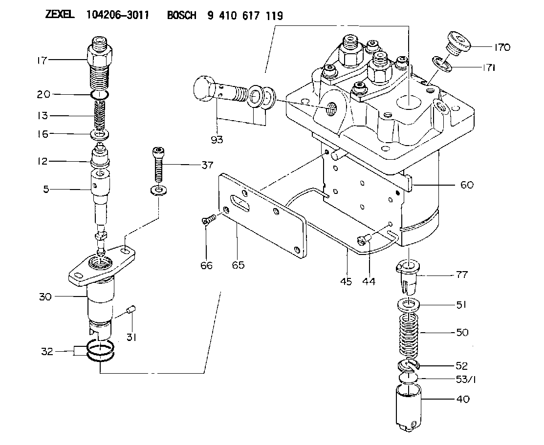
| 5. | [3] | 140161-0120 | PLUNGER-AND-BARREL ASSY |
| 12. | [3] | 140110-4420 | DELIVERY-VALVE ASSEMBLY |
| 13. | [3] | 140112-2800 | COMPRESSION SPRING |
| 16. | [3] | 140115-2200 | GASKET D12.8&8.6T0.5 |
| 17. | [3] | 140116-7220 | FITTING |
| 20. | [3] | 016550-1220 | O-RING |
| 30. | [3] | 140131-0021 | FLANGE BUSHING |
| 31. | [3] | 140271-0000 | BEARING PIN |
| 32. | [6] | 016550-1620 | O-RING |
| 37. | [6] | 140124-0100 | FLAT-HEAD SCREW |
| 40. | [3] | 140200-2320 | TAPPET |
| 44. | [3] | 140212-0300 | BEARING PIN |
| 45. | [1] | 140213-0900 | LOCKING WASHER |
| 50. | [3] | 140215-2000 | COMPRESSION SPRING |
| 51. | [3] | 140216-1300 | SLOTTED WASHER |
| 52. | [3] | 140254-2900 | SLOTTED WASHER |
| 53/1. | [1] | 140254-1400 | PLATE T1.80 |
| 53/1. | [1] | 140254-1500 | PLATE T1.85 |
| 53/1. | [1] | 140254-1600 | PLATE T1.90 |
| 53/1. | [1] | 140254-1700 | PLATE T1.95 |
| 53/1. | [1] | 140254-1800 | PLATE T2.00 |
| 53/1. | [1] | 140254-1900 | PLATE T2.05 |
| 53/1. | [1] | 140254-2000 | PLATE T2.10 |
| 53/1. | [1] | 140254-2100 | PLATE T2.15 |
| 53/1. | [1] | 140254-2200 | PLATE T2.20 |
| 53/1. | [1] | 140254-2300 | PLATE T2.25 |
| 53/1. | [1] | 140254-2400 | PLATE T2.30 |
| 53/1. | [1] | 140254-2500 | PLATE T2.35 |
| 53/1. | [1] | 140254-2600 | PLATE T2.40 |
| 53/1. | [1] | 140254-2700 | PLATE T2.45 |
| 53/1. | [1] | 140254-2800 | PLATE T2.50 |
| 53/1. | [1] | 140254-3100 | PLATE T1.825 |
| 53/1. | [1] | 140254-3200 | PLATE T1.875 |
| 53/1. | [1] | 140254-3300 | PLATE T1.925 |
| 53/1. | [1] | 140254-3400 | PLATE T1.975 |
| 53/1. | [1] | 140254-3500 | PLATE T2.025 |
| 53/1. | [1] | 140254-3600 | PLATE T2.075 |
| 53/1. | [1] | 140254-3700 | PLATE T2.125 |
| 53/1. | [1] | 140254-3800 | PLATE T2.175 |
| 53/1. | [1] | 140254-3900 | PLATE T2.225 |
| 53/1. | [1] | 140254-4000 | PLATE T2.275 |
| 53/1. | [1] | 140254-4100 | PLATE T2.325 |
| 53/1. | [1] | 140254-4200 | PLATE T2.375 |
| 53/1. | [1] | 140254-4300 | PLATE T2.425 |
| 53/1. | [1] | 140254-4400 | PLATE T2.475 |
| 53/1. | [1] | 140254-4500 | PLATE T2.525 |
| 60. | [1] | 140243-6720 | CONTROL ROD |
| 65. | [1] | 140262-1201 | PLATE |
| 66. | [4] | 140252-0000 | FLAT-HEAD SCREW |
| 77. | [3] | 140241-4021 | CONTROL SLEEVE |
| 93. | [1] | 140402-2921 | EYE BOLT |
| 170. | [1] | 140405-0100 | CAPSULE |
| 171. | [1] | 026510-1340 | GASKET D13.4&10.2T1 |
Cross reference number
Zexel num
Bosch num
Firm num
Name
104206-3011
1603251012 KUBOTA
FUEL-INJECTION PUMP
K 23MC FUEL INJECTION PUMP PFR-3MD PFR
K 23MC FUEL INJECTION PUMP PFR-3MD PFR
Information:
2. Turn the crankshaft until two pistons are at bottom center.3. Remove nuts (1) and the bearing caps. Push the rods and pistons up until the rings are out of the cylinder liners. 4. Remove pistons (2) and connecting rods from the cylinder liners.5. Do Steps 1 through 4 for the remainder of the pistons and connecting rods.Install Pistons And Connecting Rod Assemblies
1. Put clean engine oil on piston rings, connecting rod bearings and cylinder liners. 2. Use tool (A), and install piston (2) and the connecting rod in the cylinder liner. Be sure the number on the tab groove side of the connecting rod is on the opposite side from the camshaft.3. Install the bearing cap on the connecting rod with the number on the side of the bearing cap on the same side and same number as on the connecting rod.4a. For connecting rods with bolts and nuts, use the following torque procedure: Apply clean engine oil to the bolt threads, nuts, and seating faces of the bearing cap. Tighten each nut to a torque of 80 5 N m (60 4 lb.ft.). Tighten each nut an additional 120° 5°.4b. For connecting rods with only bolts, use the following torque procedure: Apply Molylube to the threads of the bolts and to the seating faces of the bearing cap and the bolt. Tighten each bolt to a torque of 90 8 N m (66 6 lb.ft.). Tighten each bolt an additional 90° 5°.5. Do Steps 1 through 4 for the remainder of the pistons and connecting rods.End By:a. install oil pumpb. install cylinder head assembly.Disassemble And Assemble Pistons And Connecting Rod Assemblies
Start By:a. remove pistons and connecting rod assemblies 1. Remove bearings (3) from the connecting rod and connecting rod cap.2. Remove retainer ring (1) and tool (A).3. Remove pin (2) and connecting rod (4) from the piston. 4. Remove piston rings (5) from the piston with tool (B). Clean the piston ring grooves on the pistons with an acceptable ring groove cleaning tool. See, Use Of Piston Pin Bearing Removal And Installation Tools, Special Instructions, Form No. SMHS7295.5. Heat connecting rod (4) in an oven to a temperature of 177° to 260° C (350° to 500° F). Never use a direct flame to heat a connecting rod. 6. Put connecting rod (4) in position on the base plate of tooling (C). Put a new rod pin bearing (6) on the adapter part of tooling (C). The old bearing is pushed out by tooling (C) as the new bearing is installed.7. Use tooling (C) to push the new bearing into the connecting rod until the push adapter of tooling (C) makes full contact with the connecting rod surface.8. Use a pin boring machine to make the rod pin bearing the correct size. The bore in the new rod pin bearing must be 50.830 0.008 mm (2.0012 .0003 in.).9. Check the clearance between the ends of the piston rings. See