Information fuel-injection pump
BOSCH
9 410 617 332
9410617332
ZEXEL
104206-3010
1042063010
KUBOTA
1603251011
1603251011

Rating:
Compare Prices: .
As an associate, we earn commssions on qualifying purchases through the links below

Fuel Pump Compatible for Kubota D905 D1005 D1105 Diesel Engine B1700 Series Tractors 16032-51011 104206-3010 9410617332
Gvgsgtyu D905 D1005 D1105 B1700 16032-51011 104206-3010 9410617332 || Easy installation: No complex debugging process required, users can use it directly, greatly saving installation time and labor costs. || Easy to maintain: The product design emphasizes practicality, easy disassembly and cleaning, effectively reducing maintenance costs and time. || Reduce vibration: During the operation of the fuel pump, it can effectively reduce vibration transmission, ensure smooth operation of the equipment, and reduce noise and wear. || Long lifespan: Through advanced manufacturing processes and high-quality materials, the service life of fuel pumps has been effectively extended, improving the overall integrity of the equipment.
Gvgsgtyu D905 D1005 D1105 B1700 16032-51011 104206-3010 9410617332 || Easy installation: No complex debugging process required, users can use it directly, greatly saving installation time and labor costs. || Easy to maintain: The product design emphasizes practicality, easy disassembly and cleaning, effectively reducing maintenance costs and time. || Reduce vibration: During the operation of the fuel pump, it can effectively reduce vibration transmission, ensure smooth operation of the equipment, and reduce noise and wear. || Long lifespan: Through advanced manufacturing processes and high-quality materials, the service life of fuel pumps has been effectively extended, improving the overall integrity of the equipment.

16032-51011 104206-3010 9410617332 Fuel Injection Pump for Kubota B1700 B7500 B2320 B2400 F2560 F2680 F2880 F3080 ZD1211 ZD331 ZD326 RTV1100 RTVX1120
HIRINTOL 🔸Replace Part Number: 16032-51011, 104206-3010, 9410617332 || 🔸Compatible Model: for Kubota Backhoe Loade B26; Tractor B2301, B2320, B2401, B2601, B2620, B2650, B2920, BX2660, BX2670, BX2680, LX2610 || 🔸Compatible Model: for Kubota UTV RTV1100CR, RTV1100CW, RTV1140, RTVX1100C, RTVX1120D, RTVX1140 || 🔸Compatible Model: for Kubota Lawn & Garden F2680, F2690, F3080, ZD326, ZD331, ZD1211 || 🔸Efficient And Stable: Using advanced technology, it can provide efficient and stable fuel supply to ensure the normal operation of the vehicle.
HIRINTOL 🔸Replace Part Number: 16032-51011, 104206-3010, 9410617332 || 🔸Compatible Model: for Kubota Backhoe Loade B26; Tractor B2301, B2320, B2401, B2601, B2620, B2650, B2920, BX2660, BX2670, BX2680, LX2610 || 🔸Compatible Model: for Kubota UTV RTV1100CR, RTV1100CW, RTV1140, RTVX1100C, RTVX1120D, RTVX1140 || 🔸Compatible Model: for Kubota Lawn & Garden F2680, F2690, F3080, ZD326, ZD331, ZD1211 || 🔸Efficient And Stable: Using advanced technology, it can provide efficient and stable fuel supply to ensure the normal operation of the vehicle.
Components :
| 0. | INJECTION-PUMP ASSEMBLY | 104206-3010 |
| 1. | _ | |
| 2. | FUEL INJECTION PUMP | |
| 3. | NUMBER PLATE | |
| 4. | _ | |
| 5. | CAPSULE | |
| 6. | ADJUSTING DEVICE | |
| 7. | NOZZLE AND HOLDER ASSY | 105148-1350 |
| 8. | Nozzle and Holder | |
| 9. | Open Pre:MPa(Kqf/cm2) | 13.2{135} |
| 10. | NOZZLE-HOLDER | 105078-0200 |
| 11. | NOZZLE | 105007-1330 |
Scheme ###:
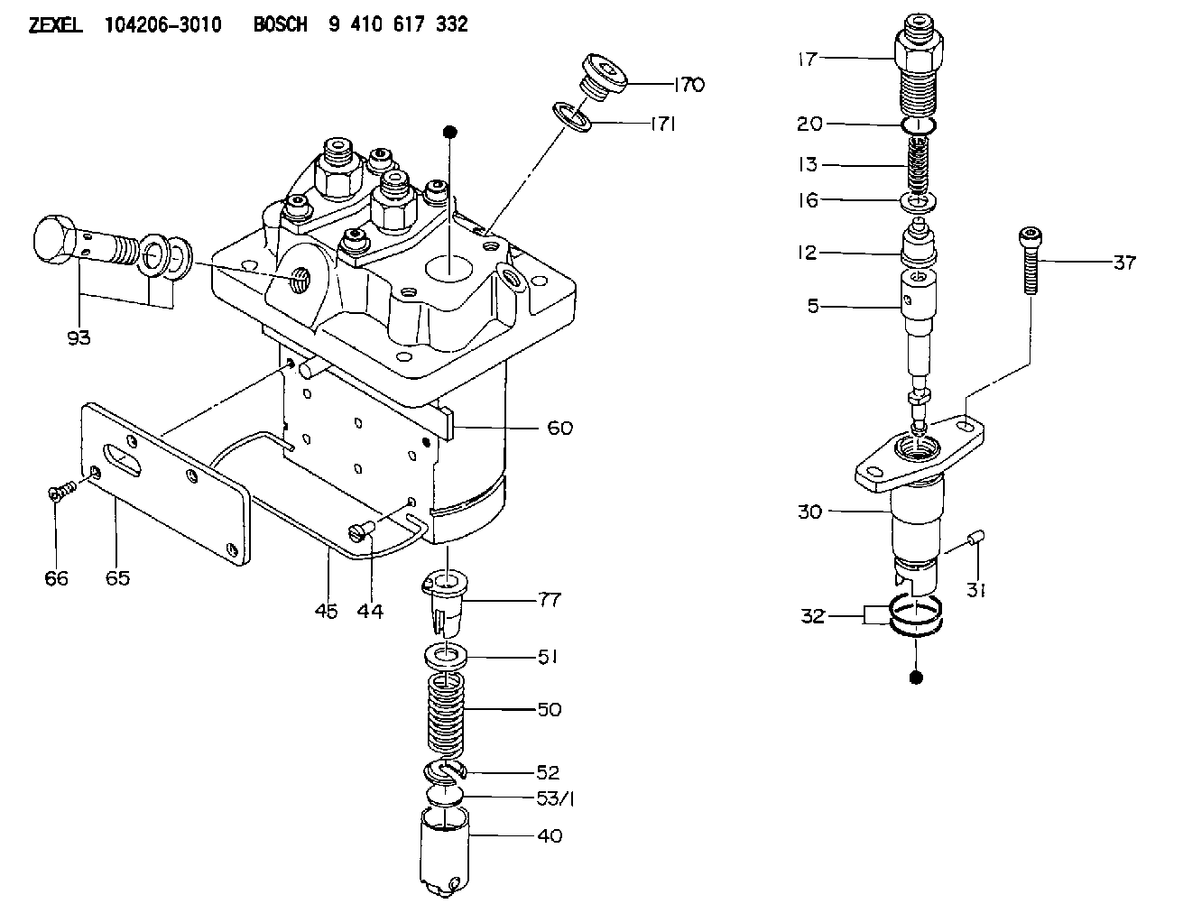
| 5. | [3] | 140154-9420 | PLUNGER-AND-BARREL ASSY |
| 12. | [3] | 140110-4420 | DELIVERY-VALVE ASSEMBLY |
| 13. | [3] | 140112-2800 | COMPRESSION SPRING |
| 16. | [3] | 140115-2200 | GASKET D12.8&8.6T0.5 |
| 17. | [3] | 140116-7220 | FITTING |
| 20. | [3] | 016550-1220 | O-RING |
| 30. | [3] | 140131-0020 | FLANGE BUSHING |
| 31. | [3] | 140271-0000 | BEARING PIN |
| 32. | [6] | 016550-1620 | O-RING |
| 37. | [6] | 140124-0100 | FLAT-HEAD SCREW |
| 40. | [3] | 140200-2320 | TAPPET |
| 44. | [3] | 140212-0300 | BEARING PIN |
| 45. | [1] | 140213-0900 | LOCKING WASHER |
| 50. | [3] | 140215-2000 | COMPRESSION SPRING |
| 51. | [3] | 140216-1300 | SLOTTED WASHER |
| 52. | [3] | 140254-2900 | SLOTTED WASHER |
| 53/1. | [1] | 140254-1400 | PLATE T1.80 |
| 53/1. | [1] | 140254-1500 | PLATE T1.85 |
| 53/1. | [1] | 140254-1600 | PLATE T1.90 |
| 53/1. | [1] | 140254-1700 | PLATE T1.95 |
| 53/1. | [1] | 140254-1800 | PLATE T2.00 |
| 53/1. | [1] | 140254-1900 | PLATE T2.05 |
| 53/1. | [1] | 140254-2000 | PLATE T2.10 |
| 53/1. | [1] | 140254-2100 | PLATE T2.15 |
| 53/1. | [1] | 140254-2200 | PLATE T2.20 |
| 53/1. | [1] | 140254-2300 | PLATE T2.25 |
| 53/1. | [1] | 140254-2400 | PLATE T2.30 |
| 53/1. | [1] | 140254-2500 | PLATE T2.35 |
| 53/1. | [1] | 140254-2600 | PLATE T2.40 |
| 53/1. | [1] | 140254-2700 | PLATE T2.45 |
| 53/1. | [1] | 140254-2800 | PLATE T2.50 |
| 53/1. | [1] | 140254-3100 | PLATE T1.825 |
| 53/1. | [1] | 140254-3200 | PLATE T1.875 |
| 53/1. | [1] | 140254-3300 | PLATE T1.925 |
| 53/1. | [1] | 140254-3400 | PLATE T1.975 |
| 53/1. | [1] | 140254-3500 | PLATE T2.025 |
| 53/1. | [1] | 140254-3600 | PLATE T2.075 |
| 53/1. | [1] | 140254-3700 | PLATE T2.125 |
| 53/1. | [1] | 140254-3800 | PLATE T2.175 |
| 53/1. | [1] | 140254-3900 | PLATE T2.225 |
| 53/1. | [1] | 140254-4000 | PLATE T2.275 |
| 53/1. | [1] | 140254-4100 | PLATE T2.325 |
| 53/1. | [1] | 140254-4200 | PLATE T2.375 |
| 53/1. | [1] | 140254-4300 | PLATE T2.425 |
| 53/1. | [1] | 140254-4400 | PLATE T2.475 |
| 53/1. | [1] | 140254-4500 | PLATE T2.525 |
| 60. | [1] | 140243-6720 | CONTROL ROD |
| 65. | [1] | 140262-1200 | PLATE |
| 66. | [4] | 140252-0000 | FLAT-HEAD SCREW |
| 77. | [3] | 140241-4021 | CONTROL SLEEVE |
| 93. | [1] | 140402-2921 | EYE BOLT |
| 170. | [1] | 140405-0100 | CAPSULE |
| 171. | [1] | 026510-1340 | GASKET D13.4&10.2T1 |
Cross reference number
Zexel num
Bosch num
Firm num
Name
Information:
Start By:a. remove flywheel The crankshaft rear seal and wear sleeve come as a set and must be installed as a set. If a replacement of the seal is to be made, a replacement of the wear sleeve must also be made. 1. Make at least three holes in seal (1) with a hammer and a sharp punch.2. Use tool (A) to remove seal (1). 3. Install tool (C) in the seal bore.4. Install tool (B) between tool (C) and wear sleeve (2). Turn tool (B) until the tool makes a dent (crease) in wear sleeve (2). Do this in three or more places until the wear sleeve is loose.5. Remove tools (B) and (C), and remove wear sleeve (2) from the crankshaft.Install Crankshaft Rear Seal And Wear Sleeve
The crankshaft seal and wear sleeve come as a set and must not be separated from each other at any time. Carefully read Special Instructions, Form No. SMHS8508, that is included with each seal and wear sleeve before any handling of the seal group is made.
1. Install the rear crankshaft seal and wear sleeve with tooling (D). Use the procedures which follow: a. Clean and make a preparation of the wear sleeve inside diameter and crankshaft outside diameter with 6V1541 Quick Cure Primer. Make an application of 9S3265 Retaining Compound to the crankshaft outside diameter before the wear sleeve is installed on the crankshaft. Do not let any Quick Cure Primer or Retaining Compound get on the lip of the seal.b. Install locator (3) and the bolts on crankshaft (4).c. The seal and wear sleeve must be installed dry. Make sure the seal is installed with the part number and the arrows showing crankshaft rotation toward the outside.
The front and rear seals and wear sleeves have different spiral grooves in the seal. Because of this type of design, the rear seal group for an engine is different from the front seal group. If a seal group is installed on the wrong side of the engine, oil can actually be taken out of the engine instead of moving the oil back into the engine.
d. Put wear sleeve (2) and seal (7) as a unit in position on locator (3).e. Put installer (5) in position on locator (3).f. Put clean engine oil on the face of nut (6) and its contact area on installer (5). Install nut (6) on locator (3).g. Tighten nut (6) until installer (5) makes contact with locator (3).h. Remove tooling (D) from the crankshaft seal and wear sleeve. Tooling (D) will install the seal and wear sleeve to the correct depth on the crankshaft.End By:a. install flywheel