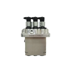
Information fuel-injection pump
BOSCH
9 410 617 332
9410617332
ZEXEL
104206-3010
1042063010
KUBOTA
1603251011
1603251011

Rating:
Compare Prices: .
As an associate, we earn commssions on qualifying purchases through the links below

Fuel Pump 16032-51011 104206-3010 9410617332,Compatible for Kubota D1105 Engine Excavator Accessories Fuel Supply System
IXICZXLT Strong structure: made of solid material, with good wear resistance. || Quality assurance: has a reliable mechanism, can effectively avoid a variety of hidden dangers. || Wide adaptation: suitable for many different types and different brands of cars, good versatility. || Pressure output: fuel pressure can be generated to ensure that fuel can be injected into the engine. || Stable performance: long-term working condition is stable, to ensure that the car continues to run normally.
IXICZXLT Strong structure: made of solid material, with good wear resistance. || Quality assurance: has a reliable mechanism, can effectively avoid a variety of hidden dangers. || Wide adaptation: suitable for many different types and different brands of cars, good versatility. || Pressure output: fuel pressure can be generated to ensure that fuel can be injected into the engine. || Stable performance: long-term working condition is stable, to ensure that the car continues to run normally.

Fuel Pump 16032-51011 104206-3010 9410617332 Compatible With Kubota D1105 Engine Excavator Accessories Fuel Supply System
KDOVANPIX Adapt to different types of engines. || Low working noise and stable operation. || Compact structure, saving installation space || Control the fuel output and stabilize the common rail pressure. || Adapt to various working conditions and provide stable pressure for the engine.
KDOVANPIX Adapt to different types of engines. || Low working noise and stable operation. || Compact structure, saving installation space || Control the fuel output and stabilize the common rail pressure. || Adapt to various working conditions and provide stable pressure for the engine.
You can express buy:
USD 631.75
14-06-2025
14-06-2025
Engine Pump Oil Pump Assembly 16032-51013 16032-51011 9410617332 104206-3010 Oil Pump Assembly 9410617332
Images:
USD 465.12

[05-May-2025]
USD 344.54

[01-May-2025]
Components :
| 0. | INJECTION-PUMP ASSEMBLY | 104206-3010 |
| 1. | _ | |
| 2. | FUEL INJECTION PUMP | |
| 3. | NUMBER PLATE | |
| 4. | _ | |
| 5. | CAPSULE | |
| 6. | ADJUSTING DEVICE | |
| 7. | NOZZLE AND HOLDER ASSY | 105148-1350 |
| 8. | Nozzle and Holder | |
| 9. | Open Pre:MPa(Kqf/cm2) | 13.2{135} |
| 10. | NOZZLE-HOLDER | 105078-0200 |
| 11. | NOZZLE | 105007-1330 |
Scheme ###:
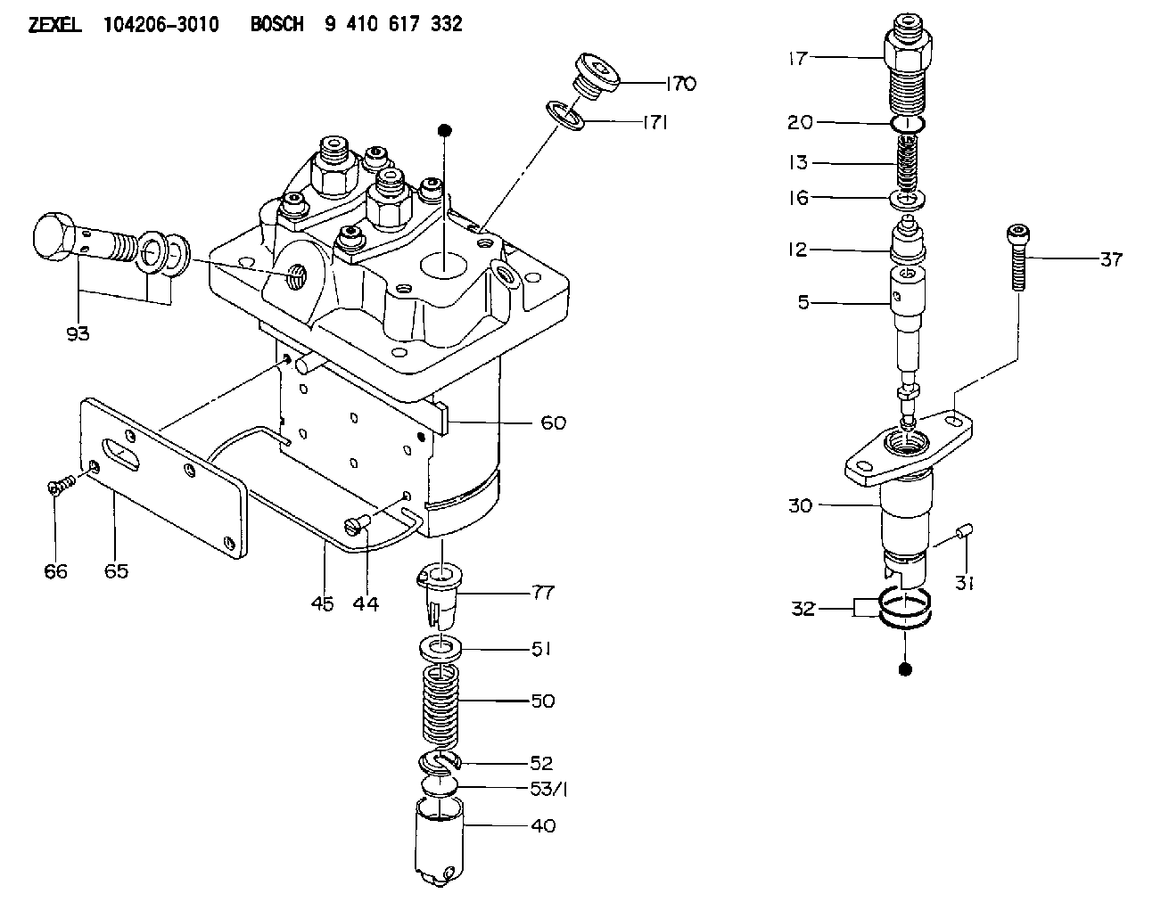
| 5. | [3] | 140154-9420 | PLUNGER-AND-BARREL ASSY |
| 12. | [3] | 140110-4420 | DELIVERY-VALVE ASSEMBLY |
| 13. | [3] | 140112-2800 | COMPRESSION SPRING |
| 16. | [3] | 140115-2200 | GASKET D12.8&8.6T0.5 |
| 17. | [3] | 140116-7220 | FITTING |
| 20. | [3] | 016550-1220 | O-RING |
| 30. | [3] | 140131-0020 | FLANGE BUSHING |
| 31. | [3] | 140271-0000 | BEARING PIN |
| 32. | [6] | 016550-1620 | O-RING |
| 37. | [6] | 140124-0100 | FLAT-HEAD SCREW |
| 40. | [3] | 140200-2320 | TAPPET |
| 44. | [3] | 140212-0300 | BEARING PIN |
| 45. | [1] | 140213-0900 | LOCKING WASHER |
| 50. | [3] | 140215-2000 | COMPRESSION SPRING |
| 51. | [3] | 140216-1300 | SLOTTED WASHER |
| 52. | [3] | 140254-2900 | SLOTTED WASHER |
| 53/1. | [1] | 140254-1400 | PLATE T1.80 |
| 53/1. | [1] | 140254-1500 | PLATE T1.85 |
| 53/1. | [1] | 140254-1600 | PLATE T1.90 |
| 53/1. | [1] | 140254-1700 | PLATE T1.95 |
| 53/1. | [1] | 140254-1800 | PLATE T2.00 |
| 53/1. | [1] | 140254-1900 | PLATE T2.05 |
| 53/1. | [1] | 140254-2000 | PLATE T2.10 |
| 53/1. | [1] | 140254-2100 | PLATE T2.15 |
| 53/1. | [1] | 140254-2200 | PLATE T2.20 |
| 53/1. | [1] | 140254-2300 | PLATE T2.25 |
| 53/1. | [1] | 140254-2400 | PLATE T2.30 |
| 53/1. | [1] | 140254-2500 | PLATE T2.35 |
| 53/1. | [1] | 140254-2600 | PLATE T2.40 |
| 53/1. | [1] | 140254-2700 | PLATE T2.45 |
| 53/1. | [1] | 140254-2800 | PLATE T2.50 |
| 53/1. | [1] | 140254-3100 | PLATE T1.825 |
| 53/1. | [1] | 140254-3200 | PLATE T1.875 |
| 53/1. | [1] | 140254-3300 | PLATE T1.925 |
| 53/1. | [1] | 140254-3400 | PLATE T1.975 |
| 53/1. | [1] | 140254-3500 | PLATE T2.025 |
| 53/1. | [1] | 140254-3600 | PLATE T2.075 |
| 53/1. | [1] | 140254-3700 | PLATE T2.125 |
| 53/1. | [1] | 140254-3800 | PLATE T2.175 |
| 53/1. | [1] | 140254-3900 | PLATE T2.225 |
| 53/1. | [1] | 140254-4000 | PLATE T2.275 |
| 53/1. | [1] | 140254-4100 | PLATE T2.325 |
| 53/1. | [1] | 140254-4200 | PLATE T2.375 |
| 53/1. | [1] | 140254-4300 | PLATE T2.425 |
| 53/1. | [1] | 140254-4400 | PLATE T2.475 |
| 53/1. | [1] | 140254-4500 | PLATE T2.525 |
| 60. | [1] | 140243-6720 | CONTROL ROD |
| 65. | [1] | 140262-1200 | PLATE |
| 66. | [4] | 140252-0000 | FLAT-HEAD SCREW |
| 77. | [3] | 140241-4021 | CONTROL SLEEVE |
| 93. | [1] | 140402-2921 | EYE BOLT |
| 170. | [1] | 140405-0100 | CAPSULE |
| 171. | [1] | 026510-1340 | GASKET D13.4&10.2T1 |
Cross reference number
Zexel num
Bosch num
Firm num
Name
Information:
Start By:a. remove flywheel The crankshaft rear seal and wear sleeve come as a set and must be installed as a set. If a replacement of the seal is to be made, a replacement of the wear sleeve must also be made. 1. Make at least three holes in seal (1) with a hammer and a sharp punch.2. Use tool (A) to remove seal (1). 3. Install tool (C) in the seal bore.4. Install tool (B) between tool (C) and wear sleeve (2). Turn tool (B) until the tool makes a dent (crease) in wear sleeve (2). Do this in three or more places until the wear sleeve is loose.5. Remove tools (B) and (C), and remove wear sleeve (2) from the crankshaft.Install Crankshaft Rear Seal And Wear Sleeve
The crankshaft seal and wear sleeve come as a set and must not be separated from each other at any time. Carefully read Special Instructions, Form No. SMHS8508, that is included with each seal and wear sleeve before any handling of the seal group is made.
1. Install the rear crankshaft seal and wear sleeve with tooling (D). Use the procedures which follow: a. Clean and make a preparation of the wear sleeve inside diameter and crankshaft outside diameter with 6V1541 Quick Cure Primer. Make an application of 9S3265 Retaining Compound to the crankshaft outside diameter before the wear sleeve is installed on the crankshaft. Do not let any Quick Cure Primer or Retaining Compound get on the lip of the seal.b. Install locator (3) and the bolts on crankshaft (4).c. The seal and wear sleeve must be installed dry. Make sure the seal is installed with the part number and the arrows showing crankshaft rotation toward the outside.
The front and rear seals and wear sleeves have different spiral grooves in the seal. Because of this type of design, the rear seal group for an engine is different from the front seal group. If a seal group is installed on the wrong side of the engine, oil can actually be taken out of the engine instead of moving the oil back into the engine.
d. Put wear sleeve (2) and seal (7) as a unit in position on locator (3).e. Put installer (5) in position on locator (3).f. Put clean engine oil on the face of nut (6) and its contact area on installer (5). Install nut (6) on locator (3).g. Tighten nut (6) until installer (5) makes contact with locator (3).h. Remove tooling (D) from the crankshaft seal and wear sleeve. Tooling (D) will install the seal and wear sleeve to the correct depth on the crankshaft.End By:a. install flywheel