Information fuel-injection pump
BOSCH
9 410 617 118
9410617118
ZEXEL
104206-3001
1042063001
KUBOTA
1603051012
1603051012

Rating:
Compare Prices: .
As an associate, we earn commssions on qualifying purchases through the links below

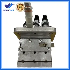
Original Fuel Injection Pump 16030-51013 Suitable for Kubota 05 Series D905 D1005 D1105 D1305 Engine 16030-51010 16030-51012
ZHLQUAMYTH Part Number: 16030-51013 16030-51010 16030-51012 104206-3002 || Engine Model: for Kubota D905 D1005 D1105 D1305 Engine || Part Type: D905 New Diesel Engine Fuel Pump || Friendly tips:This product boasts excellent performance, superior quality, reliability and safety. It is your reliable choice. || Your choice holds great significance for us. Not only do we sell products, but we also strive to provide "safety and performance assurance" for your beloved car. Your satisfaction is our eternal pursuit.We will offer the most sincere service.
ZHLQUAMYTH Part Number: 16030-51013 16030-51010 16030-51012 104206-3002 || Engine Model: for Kubota D905 D1005 D1105 D1305 Engine || Part Type: D905 New Diesel Engine Fuel Pump || Friendly tips:This product boasts excellent performance, superior quality, reliability and safety. It is your reliable choice. || Your choice holds great significance for us. Not only do we sell products, but we also strive to provide "safety and performance assurance" for your beloved car. Your satisfaction is our eternal pursuit.We will offer the most sincere service.

Fuel Injection Pump 16030-51013 104206-3002 16030-51012 16030-51010 1603051013 1042063002 1603051012 1603051010 Fits for Kubota Engine D905 D1005 D1105 D1305
Goruvhe ★Part Name★:Fuel Injection Pump || ★Part Number★:16030-51013 104206-3002 16030-51012 16030-51010 1603051013 1042063002 1603051012 1603051010 || ★Application★:Fits for Kubota Engine D905 D1005 D1105 D1305 || NOTE: To avoid unavoidable returns! Before purchasing, please compare with the old parts and part numbers to verify their accuracy before making a purchase. || Tips: The product images are for reference only. If you find any discrepancies with your actual product, please contact us promptly and we will respond as soon as possible!
Goruvhe ★Part Name★:Fuel Injection Pump || ★Part Number★:16030-51013 104206-3002 16030-51012 16030-51010 1603051013 1042063002 1603051012 1603051010 || ★Application★:Fits for Kubota Engine D905 D1005 D1105 D1305 || NOTE: To avoid unavoidable returns! Before purchasing, please compare with the old parts and part numbers to verify their accuracy before making a purchase. || Tips: The product images are for reference only. If you find any discrepancies with your actual product, please contact us promptly and we will respond as soon as possible!

16030-51013 16030-51010 16030-51012 1603051012 Fuel Injection Pump Compatible for Kubota D905 D1105 D1305 Engine
VDGOGHCN Precisely match the car model, easy to install, without complicated debugging, and can be used by direct replacement. || It can respond quickly to different working conditions of the engine, adjust the fuel injection quantity in time and ensure the smooth operation of the engine. || Accurately control the fuel injection quantity and time, so as to make the fuel burn fully, reduce the fuel consumption and improve the dynamic performance of the vehicle. || It has strong pressure output ability, which ensures that fuel can enter the engine combustion chamber accurately and efficiently, and improves combustion efficiency. || Advanced manufacturing technology and high-quality materials are adopted to effectively reduce vibration and noise during operation and ensure the stability of fuel injection process.
VDGOGHCN Precisely match the car model, easy to install, without complicated debugging, and can be used by direct replacement. || It can respond quickly to different working conditions of the engine, adjust the fuel injection quantity in time and ensure the smooth operation of the engine. || Accurately control the fuel injection quantity and time, so as to make the fuel burn fully, reduce the fuel consumption and improve the dynamic performance of the vehicle. || It has strong pressure output ability, which ensures that fuel can enter the engine combustion chamber accurately and efficiently, and improves combustion efficiency. || Advanced manufacturing technology and high-quality materials are adopted to effectively reduce vibration and noise during operation and ensure the stability of fuel injection process.
You can express buy:
USD 500
29-06-2025
29-06-2025
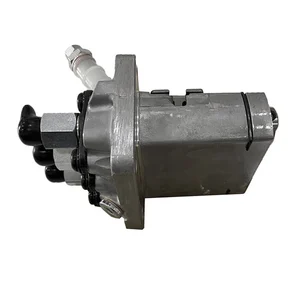
SINOCMP Injector Pump 6672389 16030-51012 104206-3002 For Kubota D1105 D1005 Bobcat 463 553 S70 E27 E26
USD 382.22
19-05-2025
19-05-2025
XCWoOshop 6672389 16030-51012 104206-3002 Fuel Injection Pump for Kubota D1105 D1005 Bobcat 463 553 S70 E27 E26
USD 1115.06
14-06-2025
14-06-2025
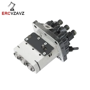
16030-51013 16030-51010 16030-51012 Fuel Injection Pump 1G872-51012 1G872-51010 for Kubota 05 Series D905 D1005 D1105 D1305
Images:
USD 561.45

[19-May-2025]
USD 728.13

[14-Jun-2025]
USD 928.2

[05-May-2025]
USD 880.11

[19-May-2025]
Components :
| 0. | INJECTION-PUMP ASSEMBLY | 104206-3001 |
| 1. | _ | |
| 2. | FUEL INJECTION PUMP | |
| 3. | NUMBER PLATE | |
| 4. | _ | |
| 5. | CAPSULE | |
| 6. | ADJUSTING DEVICE | |
| 7. | NOZZLE AND HOLDER ASSY | 105148-1350 |
| 8. | Nozzle and Holder | |
| 9. | Open Pre:MPa(Kqf/cm2) | 13.2{135} |
| 10. | NOZZLE-HOLDER | 105078-0200 |
| 11. | NOZZLE | 105007-1330 |
Scheme ###:
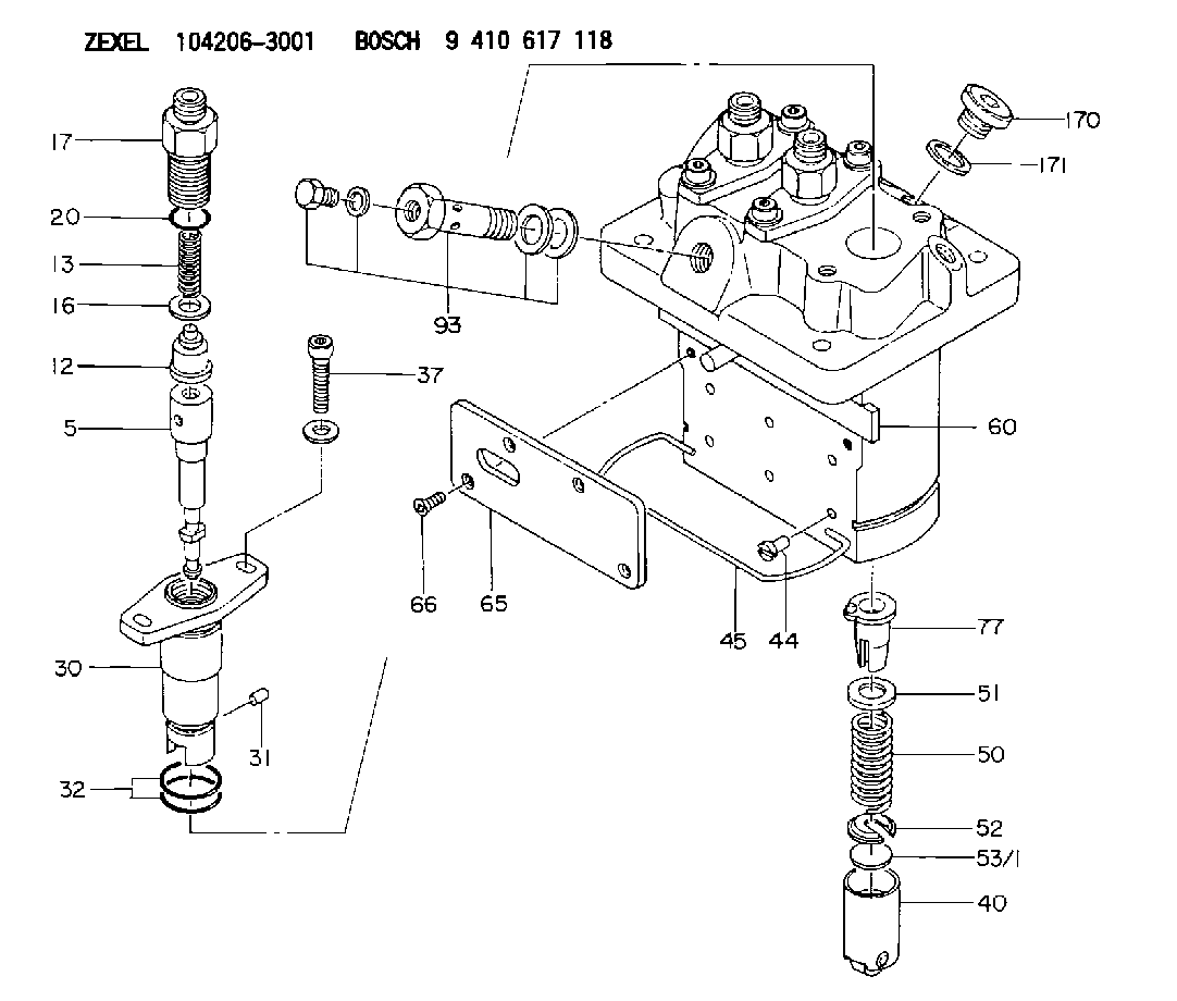
| 5. | [3] | 140161-0120 | PLUNGER-AND-BARREL ASSY |
| 12. | [3] | 140110-4420 | DELIVERY-VALVE ASSEMBLY |
| 13. | [3] | 140112-2800 | COMPRESSION SPRING |
| 16. | [3] | 140115-2200 | GASKET D12.8&8.6T0.5 |
| 17. | [3] | 140116-7220 | FITTING |
| 20. | [3] | 016550-1220 | O-RING |
| 30. | [3] | 140131-0021 | FLANGE BUSHING |
| 31. | [3] | 140271-0000 | BEARING PIN |
| 32. | [6] | 016550-1620 | O-RING |
| 37. | [6] | 140124-0100 | FLAT-HEAD SCREW |
| 40. | [3] | 140200-2320 | TAPPET |
| 44. | [3] | 140212-0300 | BEARING PIN |
| 45. | [1] | 140213-0900 | LOCKING WASHER |
| 50. | [3] | 140215-2000 | COMPRESSION SPRING |
| 51. | [3] | 140216-1300 | SLOTTED WASHER |
| 52. | [3] | 140254-2900 | SLOTTED WASHER |
| 53/1. | [1] | 140254-1400 | PLATE T1.80 |
| 53/1. | [1] | 140254-1500 | PLATE T1.85 |
| 53/1. | [1] | 140254-1600 | PLATE T1.90 |
| 53/1. | [1] | 140254-1700 | PLATE T1.95 |
| 53/1. | [1] | 140254-1800 | PLATE T2.00 |
| 53/1. | [1] | 140254-1900 | PLATE T2.05 |
| 53/1. | [1] | 140254-2000 | PLATE T2.10 |
| 53/1. | [1] | 140254-2100 | PLATE T2.15 |
| 53/1. | [1] | 140254-2200 | PLATE T2.20 |
| 53/1. | [1] | 140254-2300 | PLATE T2.25 |
| 53/1. | [1] | 140254-2400 | PLATE T2.30 |
| 53/1. | [1] | 140254-2500 | PLATE T2.35 |
| 53/1. | [1] | 140254-2600 | PLATE T2.40 |
| 53/1. | [1] | 140254-2700 | PLATE T2.45 |
| 53/1. | [1] | 140254-2800 | PLATE T2.50 |
| 53/1. | [1] | 140254-3100 | PLATE T1.825 |
| 53/1. | [1] | 140254-3200 | PLATE T1.875 |
| 53/1. | [1] | 140254-3300 | PLATE T1.925 |
| 53/1. | [1] | 140254-3400 | PLATE T1.975 |
| 53/1. | [1] | 140254-3500 | PLATE T2.025 |
| 53/1. | [1] | 140254-3600 | PLATE T2.075 |
| 53/1. | [1] | 140254-3700 | PLATE T2.125 |
| 53/1. | [1] | 140254-3800 | PLATE T2.175 |
| 53/1. | [1] | 140254-3900 | PLATE T2.225 |
| 53/1. | [1] | 140254-4000 | PLATE T2.275 |
| 53/1. | [1] | 140254-4100 | PLATE T2.325 |
| 53/1. | [1] | 140254-4200 | PLATE T2.375 |
| 53/1. | [1] | 140254-4300 | PLATE T2.425 |
| 53/1. | [1] | 140254-4400 | PLATE T2.475 |
| 53/1. | [1] | 140254-4500 | PLATE T2.525 |
| 60. | [1] | 140243-6720 | CONTROL ROD |
| 65. | [1] | 140262-1201 | PLATE |
| 66. | [4] | 140252-0000 | FLAT-HEAD SCREW |
| 77. | [3] | 140241-4021 | CONTROL SLEEVE |
| 93. | [1] | 140402-3620 | EYE BOLT |
| 170. | [1] | 140405-0100 | CAPSULE |
| 171. | [1] | 026510-1340 | GASKET D13.4&10.2T1 |
Cross reference number
Zexel num
Bosch num
Firm num
Name
104206-3001
1603051012 KUBOTA
FUEL-INJECTION PUMP
K 23MC FUEL INJECTION PUMP PFR-3MD PFR
K 23MC FUEL INJECTION PUMP PFR-3MD PFR
Information:
Start By:a. remove vibration damper
The crankshaft front seal and wear sleeve come as a set and must be installed as a set. If a replacement of the seal is to be made, a replacement of the wear sleeve must also be made.
1. Make at least three holes in seal (1) with a hammer and a sharp punch.2. Use tool (A) to remove seal (1). 3. Install tool (C) in the seal bore.4. Install tool (B) between tool (C) and wear sleeve (2). Turn tool (B) until the tool makes a dent (crease) in wear sleeve (2). Do this in three or more places until the wear sleeve is loose.5. Remove tools (B) and (C), and remove wear sleeve (2) from the crankshaft.Install Crankshaft Front Seal And Wear Sleeve
The crankshaft seal and wear sleeve come as a set and must not be separated from each other at any time. Carefully read Special Instructions, Form No. SMHS8508, that is included with each seal and wear sleeve before any handling of the seal group is made.
1. Install the front crankshaft seal and wear sleeve with tooling (D). Use the procedures which follow:a. Clean and make a preparation of the wear sleeve inside diameter and crankshaft outside diameter with 6V1541 Quick Cure Primer. Make an application of 9S3265 Retaining Compound to the crankshaft outside diameter before the wear sleeve is installed on the crankshaft. Do not let any Quick Cure Primer or Retaining Compound get on the lip of the seal.b. Install locator (3) and bolts (4) on the crankshaft.c. Seal (1) and wear sleeve (2) must be installed dry.
Make sure the seal is installed with the part number and the arrows showing crankshaft rotation toward the outside.
The front and rear seals and wear sleeves have different spiral grooves in the seal. Because of this type of design, the front seal group for an engine is different from the rear seal group. If a seal group is installed on the wrong end of the engine, oil can actually be taken out of the engine instead of moving the oil back into the engine.
d. Put wear sleeve (2) and seal (1) as a unit in position on locator (3).e. Put installer (5) in position on locator (3).f. Put clean engine oil on the face of nut (6) and its contact area on installer (5). Install nut (6) on locator (3).g. Tighten nut (6) until the inside surface of installer (5) comes in contact with locator (3).h. Remove tooling (D) from the crankshaft seal and wear sleeve. Tooling (D) will install the seal and wear sleeve to the correct depth on the crankshaft.End By:a. install vibration damper