Information fuel-injection pump
BOSCH
9 410 617 056
9410617056
ZEXEL
104205-4070
1042054070
KUBOTA
1625951011
1625951011
Rating:
Compare Prices: .
As an associate, we earn commssions on qualifying purchases through the links below

Original Fuel Injection Pump Compatible With Kubota V1505 16259-51011 104205-4070 9410617056 Excavator Engine Replacement Parts
YERCBX Low-noise operation: Optimized internal structure and materials, resulting in low noise during operation || The key components have excellent wear resistance, extending the overall service life || Integrated design: Compact structure, small space occupation, and convenient for vehicle installation and layout. || Easy maintenance: The design is reasonable, and daily inspection and maintenance operations are simple, saving time || Lightweight design: Reducing its own weight helps to achieve overall lightweighting of the vehicle
YERCBX Low-noise operation: Optimized internal structure and materials, resulting in low noise during operation || The key components have excellent wear resistance, extending the overall service life || Integrated design: Compact structure, small space occupation, and convenient for vehicle installation and layout. || Easy maintenance: The design is reasonable, and daily inspection and maintenance operations are simple, saving time || Lightweight design: Reducing its own weight helps to achieve overall lightweighting of the vehicle

Fuel Injection Pump 16259-51010 16259-51011 16259-51012 16259-51013 16259-51014 for Kubota Engine V1305 V1505 V1305-BBS
FGNTWP Part Number:16259-5101-0, 1625951010, 16259-51010, 16259-5101-1, 16259-51011, 1625951011, 1042054070, 104205-4070, 9410617056, 104205-4101, 1042054101, 9 410 617 231, 1625951013, 16259-51013, 16259-5101-3, 1625951014, 16259-51014, 16259-5101-4, 1625951012, 16259-51012, 16259-5101-2, 9 410 617 329, 9410617329, 104205-4100, 1042054100 || Application:Fit for Kubota Engine: V1305, V1505, V1305-BBS
FGNTWP Part Number:16259-5101-0, 1625951010, 16259-51010, 16259-5101-1, 16259-51011, 1625951011, 1042054070, 104205-4070, 9410617056, 104205-4101, 1042054101, 9 410 617 231, 1625951013, 16259-51013, 16259-5101-3, 1625951014, 16259-51014, 16259-5101-4, 1625951012, 16259-51012, 16259-5101-2, 9 410 617 329, 9410617329, 104205-4100, 1042054100 || Application:Fit for Kubota Engine: V1305, V1505, V1305-BBS

IMIFAFTAbT 16259-51011 104205-4070 9410617056 16259-51010 Fuel injection pump Fits for Kubota Engine V1305 V1505
IMIFAFTAbT Product Name: 16259-51011 104205-4070 9410617056 16259-51010 Fuel injection pump || Part number: 16259-51011 104205-4070 9410617056 16259-51010 || Fits for Kubota Engine V1305 V1505 || 1 PCS Fuel injection pump || Note: Please confirm that the product shown in the part number is what you need. If you cannot confirm you can leave us a message and provide your engine serial number and nameplate
IMIFAFTAbT Product Name: 16259-51011 104205-4070 9410617056 16259-51010 Fuel injection pump || Part number: 16259-51011 104205-4070 9410617056 16259-51010 || Fits for Kubota Engine V1305 V1505 || 1 PCS Fuel injection pump || Note: Please confirm that the product shown in the part number is what you need. If you cannot confirm you can leave us a message and provide your engine serial number and nameplate
You can express buy:
USD 420.9
26-06-2025
26-06-2025
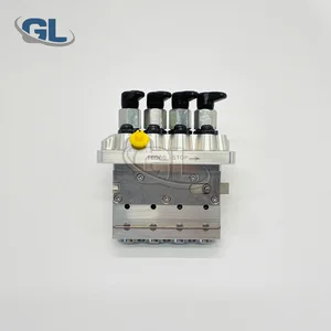
China Made New Fuel Injection Pump 16259-51011 104205-4070 9410617056 compatible for Kubota V1505
Components :
| 0. | INJECTION-PUMP ASSEMBLY | 104205-4070 |
| 1. | _ | |
| 2. | FUEL INJECTION PUMP | |
| 3. | NUMBER PLATE | |
| 4. | _ | |
| 5. | CAPSULE | |
| 6. | ADJUSTING DEVICE | |
| 7. | NOZZLE AND HOLDER ASSY | |
| 8. | Nozzle and Holder | |
| 9. | Open Pre:MPa(Kqf/cm2) | |
| 10. | NOZZLE-HOLDER | |
| 11. | NOZZLE |
Scheme ###:
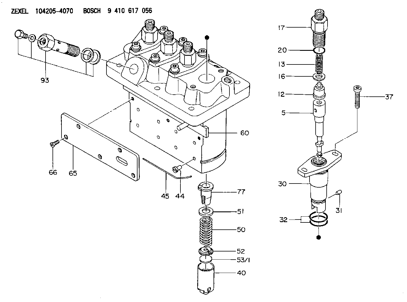
| 5. | [4] | 140154-0720 | PLUNGER-AND-BARREL ASSY |
| 12. | [4] | 140110-4420 | DELIVERY-VALVE ASSEMBLY |
| 13. | [4] | 140112-2800 | COMPRESSION SPRING |
| 16. | [4] | 140115-2200 | GASKET D12.8&8.6T0.5 |
| 17. | [4] | 140116-7220 | FITTING |
| 20. | [4] | 016550-1220 | O-RING |
| 30. | [4] | 140131-0020 | FLANGE BUSHING |
| 31. | [4] | 140271-0000 | BEARING PIN |
| 32. | [8] | 016550-1620 | O-RING |
| 37. | [8] | 140124-0100 | FLAT-HEAD SCREW |
| 40. | [4] | 140200-2320 | TAPPET |
| 44. | [4] | 140212-0300 | BEARING PIN |
| 45. | [1] | 140213-1200 | LOCKING WASHER |
| 50. | [4] | 140215-2000 | COMPRESSION SPRING |
| 51. | [4] | 140216-1300 | SLOTTED WASHER |
| 52. | [4] | 140254-2900 | SLOTTED WASHER |
| 53/1. | [1] | 140254-1400 | PLATE T1.80 |
| 53/1. | [1] | 140254-1500 | PLATE T1.85 |
| 53/1. | [1] | 140254-1600 | PLATE T1.90 |
| 53/1. | [1] | 140254-1700 | PLATE T1.95 |
| 53/1. | [1] | 140254-1800 | PLATE T2.00 |
| 53/1. | [1] | 140254-1900 | PLATE T2.05 |
| 53/1. | [1] | 140254-2000 | PLATE T2.10 |
| 53/1. | [1] | 140254-2100 | PLATE T2.15 |
| 53/1. | [1] | 140254-2200 | PLATE T2.20 |
| 53/1. | [1] | 140254-2300 | PLATE T2.25 |
| 53/1. | [1] | 140254-2400 | PLATE T2.30 |
| 53/1. | [1] | 140254-2500 | PLATE T2.35 |
| 53/1. | [1] | 140254-2600 | PLATE T2.40 |
| 53/1. | [1] | 140254-2700 | PLATE T2.45 |
| 53/1. | [1] | 140254-2800 | PLATE T2.50 |
| 53/1. | [1] | 140254-3100 | PLATE T1.825 |
| 53/1. | [1] | 140254-3200 | PLATE T1.875 |
| 53/1. | [1] | 140254-3300 | PLATE T1.925 |
| 53/1. | [1] | 140254-3400 | PLATE T1.975 |
| 53/1. | [1] | 140254-3500 | PLATE T2.025 |
| 53/1. | [1] | 140254-3600 | PLATE T2.075 |
| 53/1. | [1] | 140254-3700 | PLATE T2.125 |
| 53/1. | [1] | 140254-3800 | PLATE T2.175 |
| 53/1. | [1] | 140254-3900 | PLATE T2.225 |
| 53/1. | [1] | 140254-4000 | PLATE T2.275 |
| 53/1. | [1] | 140254-4100 | PLATE T2.325 |
| 53/1. | [1] | 140254-4200 | PLATE T2.375 |
| 53/1. | [1] | 140254-4300 | PLATE T2.425 |
| 53/1. | [1] | 140254-4400 | PLATE T2.475 |
| 53/1. | [1] | 140254-4500 | PLATE T2.525 |
| 60. | [1] | 140243-4820 | CONTROL ROD |
| 65. | [1] | 140262-0600 | PLATE |
| 66. | [5] | 140252-0000 | FLAT-HEAD SCREW |
| 77. | [4] | 140241-4020 | CONTROL SLEEVE |
| 93. | [1] | 140402-2721 | EYE BOLT |
Cross reference number
Zexel num
Bosch num
Firm num
Name
Information:
Start By:a. remove cylinder headb. remove front and rear housingsc. remove rear seal and carrierd. remove pistons and connecting rods 1. Remove bolts (1), remove main bearing caps (2) and remove thrust bearings (3) from the center main. 2. Install two bolts and nylon strap (4) then carefully, remove the crankshaft. The approximate weight of the crankshaft is 129 Kg (284 lbs.).3. Remove the upper portions of the main bearings. The following steps are for the installation of the crankshaft. Be sure main bearing tabs engage the grooves in the block and cap.4. Position the upper portion of the main bearings in the block and the lower main bearing portion in caps (2). Make sure everything is clean and only the bearing face is lubricated with engine oil.5. Position the crankshaft. 6. Install thrust bearings (3).7. Install main bearing caps (2). Put engine oil or molylube on the bolt threads and the washer face, then install bolts (1). Tighten the bolts on the side where the main bearing tabs are located to a torque of 95 5 N m (70 4 lb.ft.). Tighten the bolts on the opposite side to a torque of 95 5 N m (70 4 lb.ft.).8. Put mark on each bolt head and the bearing caps. Turn the bolts that are opposite the main bearing tabs an additional 90° 5° turn. Then turn the bolts on the side where the main bearing tabs are located an additional 90° 5° turn.
Typical Example9. Use tooling (A) to measure crankshaft end play. The crankshaft end play must be 0.1 to 0.5 mm (.004 to .020 in.).End By:a. install pistons and connecting rodsb. install rear seal and carrierc. install front and rear housingsd. install cylinder head
Typical Example9. Use tooling (A) to measure crankshaft end play. The crankshaft end play must be 0.1 to 0.5 mm (.004 to .020 in.).End By:a. install pistons and connecting rodsb. install rear seal and carrierc. install front and rear housingsd. install cylinder head