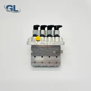
Information fuel-injection pump
BOSCH
9 410 617 326
9410617326
ZEXEL
104205-4051
1042054051
KUBOTA
1628251011
1628251011

Rating:
Compare Prices: .
As an associate, we earn commssions on qualifying purchases through the links below

Original Fuel Injection Pump Compatible With Kubota V1505 16282-51011 104205-4051 9410617326 Excavator Engine Replacement Parts
YERCBX The key components have excellent wear resistance, extending the overall service life || Integrated design: Compact structure, small space occupation, and convenient for vehicle installation and layout. || Easy maintenance: The design is reasonable, and daily inspection and maintenance operations are simple, saving time || Lightweight design: Reducing its own weight helps to achieve overall lightweighting of the vehicle || The installation interface design is convenient for installation and saves installation time.
YERCBX The key components have excellent wear resistance, extending the overall service life || Integrated design: Compact structure, small space occupation, and convenient for vehicle installation and layout. || Easy maintenance: The design is reasonable, and daily inspection and maintenance operations are simple, saving time || Lightweight design: Reducing its own weight helps to achieve overall lightweighting of the vehicle || The installation interface design is convenient for installation and saves installation time.

WZCNLXLX Fuel Injection Pump 16282-51011 104205-4051 9410617326 For Kubota V1505 Engine
WZCNLXLX Item Name:Fuel Injection Pump || Item Number:16282-51011 104205-4051 9410617326 1628251011 1042054051 || Application:For Kubota V1505 Engine || Note: If you are unsure if the product is suitable.In order not to delay your use of the parts, please provide your engine nameplate or serial number and part number, and we will help you confirm if it is suitable. To avoid unnecessary returns, please check the product image and part number to ensure it is the product you want. || Tip: Please contact us - we are a professional sales team and we have many products to offer to you. Many buyers are very satisfied with our service. You can get first-class products and high-quality services from us, believe me, you will have a pleasant shopping experience here.
WZCNLXLX Item Name:Fuel Injection Pump || Item Number:16282-51011 104205-4051 9410617326 1628251011 1042054051 || Application:For Kubota V1505 Engine || Note: If you are unsure if the product is suitable.In order not to delay your use of the parts, please provide your engine nameplate or serial number and part number, and we will help you confirm if it is suitable. To avoid unnecessary returns, please check the product image and part number to ensure it is the product you want. || Tip: Please contact us - we are a professional sales team and we have many products to offer to you. Many buyers are very satisfied with our service. You can get first-class products and high-quality services from us, believe me, you will have a pleasant shopping experience here.
You can express buy:
USD 420
28-05-2025
28-05-2025
China Made New Fuel Injection Pump 16282-51011 104205-4051 9410617326 compatible for Kubota V1505
Components :
| 0. | INJECTION-PUMP ASSEMBLY | 104205-4051 |
| 1. | _ | |
| 2. | FUEL INJECTION PUMP | |
| 3. | NUMBER PLATE | |
| 4. | _ | |
| 5. | CAPSULE | |
| 6. | ADJUSTING DEVICE | |
| 7. | NOZZLE AND HOLDER ASSY | |
| 8. | Nozzle and Holder | |
| 9. | Open Pre:MPa(Kqf/cm2) | |
| 10. | NOZZLE-HOLDER | |
| 11. | NOZZLE |
Scheme ###:
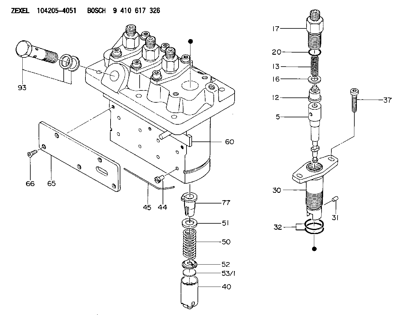
| 5. | [4] | 140154-1420 | PLUNGER-AND-BARREL ASSY |
| 12. | [4] | 140110-4420 | DELIVERY-VALVE ASSEMBLY |
| 13. | [4] | 140112-2800 | COMPRESSION SPRING |
| 16. | [4] | 140115-2200 | GASKET D12.8&8.6T0.5 |
| 17. | [4] | 140116-7220 | FITTING |
| 20. | [4] | 016550-1220 | O-RING |
| 30. | [4] | 140131-0020 | FLANGE BUSHING |
| 31. | [4] | 140271-0000 | BEARING PIN |
| 32. | [8] | 016550-1620 | O-RING |
| 37. | [8] | 140124-0100 | FLAT-HEAD SCREW |
| 40. | [4] | 140200-2320 | TAPPET |
| 44. | [4] | 140212-0300 | BEARING PIN |
| 45. | [1] | 140213-1200 | LOCKING WASHER |
| 50. | [4] | 140215-2000 | COMPRESSION SPRING |
| 51. | [4] | 140216-1300 | SLOTTED WASHER |
| 52. | [4] | 140254-2900 | SLOTTED WASHER |
| 53/1. | [1] | 140254-1400 | PLATE T1.80 |
| 53/1. | [1] | 140254-1500 | PLATE T1.85 |
| 53/1. | [1] | 140254-1600 | PLATE T1.90 |
| 53/1. | [1] | 140254-1700 | PLATE T1.95 |
| 53/1. | [1] | 140254-1800 | PLATE T2.00 |
| 53/1. | [1] | 140254-1900 | PLATE T2.05 |
| 53/1. | [1] | 140254-2000 | PLATE T2.10 |
| 53/1. | [1] | 140254-2100 | PLATE T2.15 |
| 53/1. | [1] | 140254-2200 | PLATE T2.20 |
| 53/1. | [1] | 140254-2300 | PLATE T2.25 |
| 53/1. | [1] | 140254-2400 | PLATE T2.30 |
| 53/1. | [1] | 140254-2500 | PLATE T2.35 |
| 53/1. | [1] | 140254-2600 | PLATE T2.40 |
| 53/1. | [1] | 140254-2700 | PLATE T2.45 |
| 53/1. | [1] | 140254-2800 | PLATE T2.50 |
| 53/1. | [1] | 140254-3100 | PLATE T1.825 |
| 53/1. | [1] | 140254-3200 | PLATE T1.875 |
| 53/1. | [1] | 140254-3300 | PLATE T1.925 |
| 53/1. | [1] | 140254-3400 | PLATE T1.975 |
| 53/1. | [1] | 140254-3500 | PLATE T2.025 |
| 53/1. | [1] | 140254-3600 | PLATE T2.075 |
| 53/1. | [1] | 140254-3700 | PLATE T2.125 |
| 53/1. | [1] | 140254-3800 | PLATE T2.175 |
| 53/1. | [1] | 140254-3900 | PLATE T2.225 |
| 53/1. | [1] | 140254-4000 | PLATE T2.275 |
| 53/1. | [1] | 140254-4100 | PLATE T2.325 |
| 53/1. | [1] | 140254-4200 | PLATE T2.375 |
| 53/1. | [1] | 140254-4300 | PLATE T2.425 |
| 53/1. | [1] | 140254-4400 | PLATE T2.475 |
| 53/1. | [1] | 140254-4500 | PLATE T2.525 |
| 60. | [1] | 140243-4820 | CONTROL ROD |
| 65. | [1] | 140262-0600 | PLATE |
| 66. | [5] | 140252-0000 | FLAT-HEAD SCREW |
| 77. | [4] | 140241-4021 | CONTROL SLEEVE |
| 93. | [1] | 140402-2921 | EYE BOLT |
Cross reference number
Zexel num
Bosch num
Firm num
Name
Information:
Turn the engine to (TDC) top center compression stroke for the No. 1 piston and install crankshaft flywheel timing pin. This will help when timing the camshaft when installing.
Wire used to hold cam roller followers up off camshaft. It is not necessary to remove the cylinder head. With the cylinder head in place, just wire the cam roller followers up off the camshaft and then remove the camshaft. 1. Remove camshaft retainer bolt (1) and remove camshaft assembly (2). The following steps are for the installation of the camshaft assembly. When installing the camshaft, rotating it both clockwise and counter clockwise directions will help prevent it from binding in the bearing bores.2. Put engine oil on the lobes and journals of the camshaft. Carefully install the camshaft. When installing the camshaft, be sure the number one cylinder is at (TDC) top dead center of the compression stroke with the timing pin installed in the flywheel. Camshaft timing is very important. Cam gear timing marks must line up with idler gear timing marks as illustrated. For more information about timing of engine, refer to SPECIFICATIONS module, FORM No. SENR3908.
Camshaft Timing3. With the camshaft properly timed and positioned, install retaining bolt (1). Tighten bolt (1) to a torque of 48 7 N m (35 5 lb.ft.). Remove the wire that was used to hold the cam roller followers up off the camshaftEnd By:a. install fuel transfer pumpb. install front coverc. install front pulley and damperd. install fuel injectorse. install rocker arm assemblies and push rodsDisassembly And Assembly of Camshaft And Gear/Weight Assembly
If the disassembly is being done, just to replace any or all of the twelve retainers, then it may not be necessary to remove the weight assembly from the camshaft. Depending on the press set-up, the retainers may be removed and installed with the camshaft and weight assembly still assembled.Start By:a. remove camshaft assembly 1. Wrap camshaft portion of camshaft and gear/weight assembly (1) with paper towels (2) to protect the camshaft from being damaged. Remove bolts (3) and remove cover plate (4) from assembly (1). Care must be taken not to damage the timing/speed sensor ring gear when removing. Using the prybar, work around the ring gear and pry the ring gear off a little at a time. 2. Using a prybar, carefully pry timing/speed sensor ring gear (5) off the gear/weight assembly. 3. Reposition the camshaft and gear/weight assembly. Remove bolts (6) and remove retainer ring (7), then remove cam gear (8).
Care must be taken not to allow the camshaft to fall to the floor when pressing it from the weight. Also be sure that a camshaft lobe does not catch on the press plates.
4. Place the camshaft and weight assembly through spacer pipe (10) and place it in the press as illustrated. Press the camshaft from weight assembly (9). 5. Position weight assembly (9) in press as illustrated. Use a small spacer pipe (11) to support weight (9) and with a block on