Information fuel-injection pump
BOSCH
F 01G 09Y 01Y
f01g09y01y
ZEXEL
104205-3150
1042053150
KUBOTA
1G82051013
1g82051013
Rating:
Compare Prices: .
As an associate, we earn commssions on qualifying purchases through the links below

YQABLE Fuel Injection Pump 1G820-51013 Compatible with Kubota Engine D902 Excavator KX41 U15 KX41-3 U15-3
YQABLE New Aftermarket Replacement Parts || Part Number: 1G820-51013, 104205-3131, F01G09Y01Y, 104205-3150, 1042053131, 1042053150, 1G82051013, 1G820-51010, 1G82051010, 104205-3132, 1042053132, 1G820-5101-0, 1G820-5101-3, 1G820-51012, 1G82051012, 1G820-5101-2 || Compatible with Kubota Engine:D902. Compatible with Kubota Excavator:KX41, U15, KX41-3, U15-3 || Please make sure the OE number matches the part you are replacing || Please be very careful to check our photos, make sure the photo showed is same as you wanted. Kindly get in touch with us at any time if you have any questions
YQABLE New Aftermarket Replacement Parts || Part Number: 1G820-51013, 104205-3131, F01G09Y01Y, 104205-3150, 1042053131, 1042053150, 1G82051013, 1G820-51010, 1G82051010, 104205-3132, 1042053132, 1G820-5101-0, 1G820-5101-3, 1G820-51012, 1G82051012, 1G820-5101-2 || Compatible with Kubota Engine:D902. Compatible with Kubota Excavator:KX41, U15, KX41-3, U15-3 || Please make sure the OE number matches the part you are replacing || Please be very careful to check our photos, make sure the photo showed is same as you wanted. Kindly get in touch with us at any time if you have any questions

Fuel Injection Pump 1G820-51013 for Kubota Engine D902 Excavator KX41 U15 KX41-3 U15-3
FGNTWP Part Number:1G820-51013, 104205-3131, F01G09Y01Y, 104205-3150, 1042053131, 1042053150, 1G82051013, 1G820-51010, 1G82051010, 104205-3132, 1042053132, 1G820-5101-0, 1G820-5101-3, 1G820-51012, 1G82051012, 1G820-5101-2 || Applications:Fit For Kubota Excavator:KX41, U15, KX41-3, U15-3
FGNTWP Part Number:1G820-51013, 104205-3131, F01G09Y01Y, 104205-3150, 1042053131, 1042053150, 1G82051013, 1G820-51010, 1G82051010, 104205-3132, 1042053132, 1G820-5101-0, 1G820-5101-3, 1G820-51012, 1G82051012, 1G820-5101-2 || Applications:Fit For Kubota Excavator:KX41, U15, KX41-3, U15-3
Components :
| 0. | INJECTION-PUMP ASSEMBLY | 104205-3150 |
| 1. | _ | |
| 2. | FUEL INJECTION PUMP | |
| 3. | NUMBER PLATE | |
| 4. | _ | |
| 5. | CAPSULE | |
| 6. | ADJUSTING DEVICE | |
| 7. | NOZZLE AND HOLDER ASSY | |
| 8. | Nozzle and Holder | |
| 9. | Open Pre:MPa(Kqf/cm2) | |
| 10. | NOZZLE-HOLDER | |
| 11. | NOZZLE |
Scheme ###:
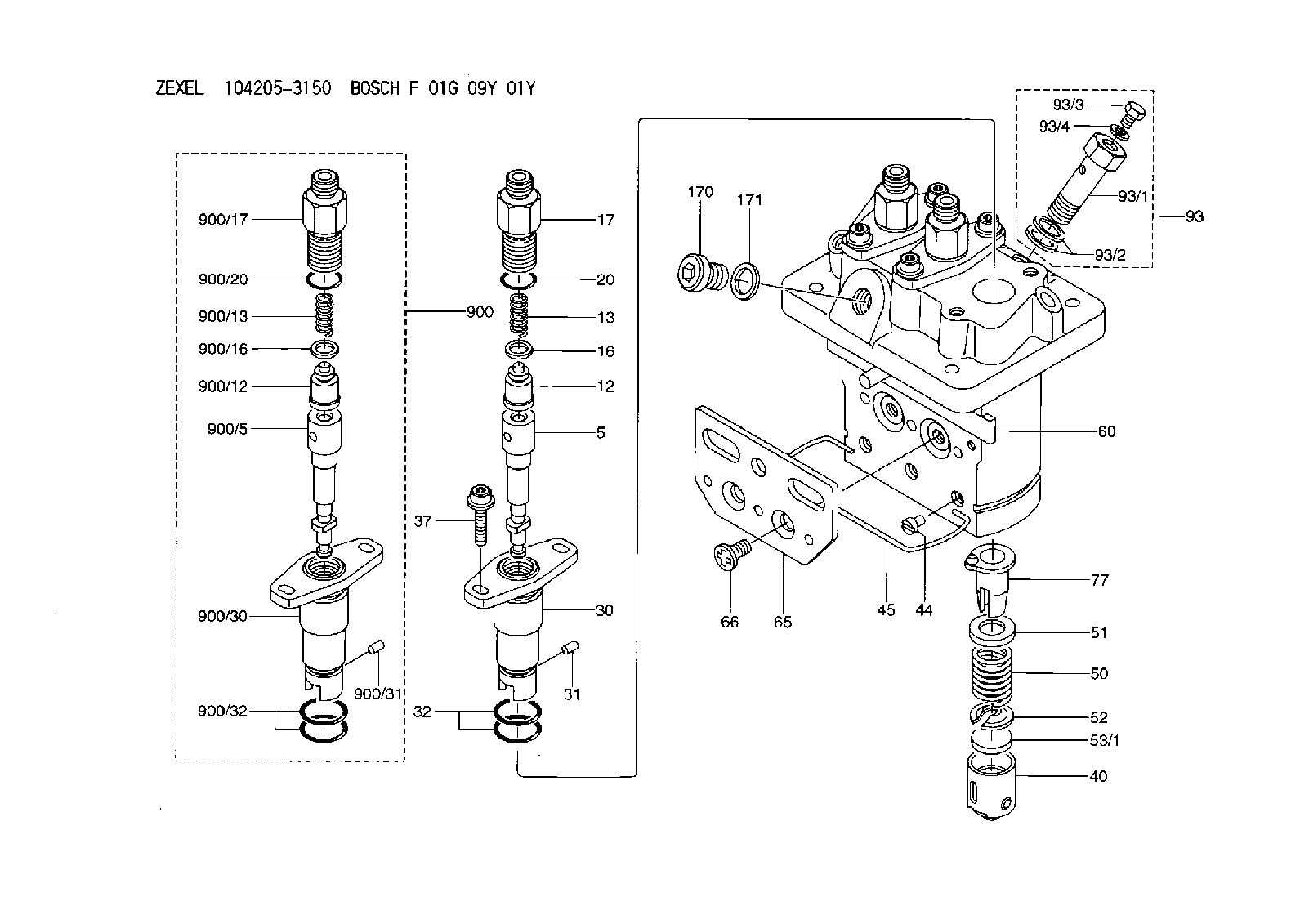
| 5. | [3] | 140154-1720 | PLUNGER-AND-BARREL ASSY M20 |
| 12. | [3] | 140110-4420 | DELIVERY-VALVE ASSEMBLY K25 |
| 13. | [3] | 140112-2800 | COMPRESSION SPRING |
| 16. | [3] | 140115-2200 | GASKET |
| 17. | [3] | 140116-7820 | FITTING |
| 20. | [3] | 140118-0500 | O-RING |
| 30. | [3] | 140131-0021 | FLANGE BUSHING |
| 31. | [3] | 140271-0000 | BEARING PIN |
| 32. | [6] | 140118-0400 | O-RING |
| 37. | [6] | 140124-0100 | FLAT-HEAD SCREW |
| 40. | [3] | 140200-2320 | TAPPET |
| 44. | [3] | 140212-0300 | BEARING PIN |
| 45. | [1] | 140213-0900 | LOCKING WASHER |
| 50. | [3] | 140215-2000 | COMPRESSION SPRING |
| 51. | [3] | 140216-1300 | SLOTTED WASHER |
| 52. | [3] | 140254-2900 | SLOTTED WASHER |
| 53/1. | [1] | 140254-1400 | PLATE T1.80 |
| 53/1. | [1] | 140254-1500 | PLATE T1.85 |
| 53/1. | [1] | 140254-1600 | PLATE T1.90 |
| 53/1. | [1] | 140254-1700 | PLATE T1.95 |
| 53/1. | [1] | 140254-1800 | PLATE T2.00 |
| 53/1. | [1] | 140254-1900 | PLATE T2.05 |
| 53/1. | [1] | 140254-2000 | PLATE T2.10 |
| 53/1. | [1] | 140254-2100 | PLATE T2.15 |
| 53/1. | [1] | 140254-2200 | PLATE T2.20 |
| 53/1. | [1] | 140254-2300 | PLATE T2.25 |
| 53/1. | [1] | 140254-2400 | PLATE T2.30 |
| 53/1. | [1] | 140254-2500 | PLATE T2.35 |
| 53/1. | [1] | 140254-2600 | PLATE T2.40 |
| 53/1. | [1] | 140254-2700 | PLATE T2.45 |
| 53/1. | [1] | 140254-2800 | PLATE T2.50 |
| 53/1. | [1] | 140254-3100 | PLATE T1.825 |
| 53/1. | [1] | 140254-3200 | PLATE T1.875 |
| 53/1. | [1] | 140254-3300 | PLATE T1.925 |
| 53/1. | [1] | 140254-3400 | PLATE T1.975 |
| 53/1. | [1] | 140254-3500 | PLATE T2.025 |
| 53/1. | [1] | 140254-3600 | PLATE T2.075 |
| 53/1. | [1] | 140254-3700 | PLATE T2.125 |
| 53/1. | [1] | 140254-3800 | PLATE T2.175 |
| 53/1. | [1] | 140254-3900 | PLATE T2.225 |
| 53/1. | [1] | 140254-4000 | PLATE T2.275 |
| 53/1. | [1] | 140254-4100 | PLATE T2.325 |
| 53/1. | [1] | 140254-4200 | PLATE T2.375 |
| 53/1. | [1] | 140254-4300 | PLATE T2.425 |
| 53/1. | [1] | 140254-4400 | PLATE T2.475 |
| 53/1. | [1] | 140254-4500 | PLATE T2.525 |
| 60. | [1] | 140243-7620 | CONTROL ROD |
| 65. | [1] | 140262-1800 | PLATE |
| 66. | [2] | 140252-0300 | FLAT-HEAD SCREW |
| 77. | [3] | 140241-4021 | CONTROL SLEEVE |
| 93. | [1] | 140402-3020 | EYE BOLT |
| 93/1. | [1] | 140402-3000 | EYE BOLT |
| 93/2. | [2] | 026510-1340 | GASKET |
| 93/3. | [1] | 140420-2400 | BLEEDER SCREW |
| 93/4. | [1] | 026506-1040 | GASKET |
| 170. | [1] | 140405-0100 | CAPSULE |
| 171. | [1] | 026510-1340 | GASKET |
| 900. | [3] | 140191-0720 | PLUNGER-AND-BARREL ASSY |
| 900/5. | [3] | 140154-1720 | PLUNGER-AND-BARREL ASSY M20 |
| 900/12. | [3] | 140110-4420 | DELIVERY-VALVE ASSEMBLY K25 |
| 900/13. | [3] | 140112-2800 | COMPRESSION SPRING |
| 900/16. | [3] | 140115-2200 | GASKET |
| 900/17. | [3] | 140116-7820 | FITTING |
| 900/20. | [3] | 140118-0500 | O-RING |
| 900/30. | [3] | 140131-0021 | FLANGE BUSHING |
| 900/31. | [3] | 140271-0000 | BEARING PIN |
| 900/32. | [6] | 140118-0400 | O-RING |
Include in #1:
103684-0250
as _
Include in #2:
104205-3150
as INJECTION-PUMP ASSEMBLY
Cross reference number
Zexel num
Bosch num
Firm num
Name
Information:
Step 8. Check Signal Voltage At ECMA. Install the 40-Pin Breakout 'T' at the ECM Connector (J4/P4).B. Measure the voltage between Fuel Pressure, Pin 39 and Sensor Return Analog, Pin 35. The signal voltage should correspond to the observed fuel pressure reading shown in Table A. OK: The Fuel Pressure Signal is reaching the ECM. If Step 3 found that the ECM is not reading fuel pressure correctly, then the ECM is defective. Replace the ECM. Stop. NOT OK: The signal was good at the sensor but did not reach the ECM. Repair the wiring harness between Fuel Pressure Sensor and the ECM. Stop.P227: Retarder Enable Signal Test
The "Retarder Enable" signal is provided by the ECM to indicate that conditions are acceptable for an engine retarder to operate. Operation of the retarder is inhibited during undesirable engine operating conditions (such as while the engine is being fueled).With the Cruise Control ON/OFF Switch in the OFF position, the retarder is enabled under the following conditions:* engine rpm is greater than 950 rpm and* driver's foot is off the throttle pedal and the clutch pedalWith the Cruise Control ON/OFF Switch "ON", the operation of the retarder is also controlled through the customer parameter "Engine Retarder Mode". Programming the parameter to "COAST" allows retarding with the service brakes applied, but allows the engine to coast with no retarding after they are released. Programming the parameter to "LATCH" allows retarding with the service brake applied and keeps the retarder latched on after the service brakes are released (until engine rpm drops below 950 rpm or the driver presses the throttle or clutch pedal).The Retarder Enable Signal should be 15% Duty Cycle (nominal) to indicate that the retarder is enabled and 85% Duty Cycle (nominal) to indicate that it is disabled. The remainder of the engine retarder circuit is supplied by the OEM. In typical installations, the Retarder Enable signal isused by a separate Brake Control Module, which then energize the retarder solenoids. An "Engine Brake On" Switch is also typically connected to the Brake Control Module, and must be ON before the brake will operate. Step 1. Inspect Connectors And Wiring HarnessInspect the Vehicle Connector (J7/P7) and the ECM Connector (J4/P4) connections and wiring between, being sure to:* Check Connector lock rings.* Perform 10 pound pull test on each pin or wire.* Inspect wiring for damage or abrasion.* Inspect connectors for damage or corrosion. Refer to P-201: Inspecting Electrical Connectors for details. Repair any damage, then continue with the next step.Step 2. Verify Throttle Position And Clutch Switch InputsA. Use P-303: Throttle Position Sensor Adjustment procedure to verify correct adjustment of the throttle pedal. The "Throttle Position Signal" must be less than 7% at low idle, to perform the remainder of this test procedure.B. Use P-215: Service Brake And Clutch Switch Test, to verify correct adjustment and operation of the Clutch Pedal Switch. Clutch Switch Status must be OFF, with foot off the clutch, to perform the remainder of this test procedure.Step
The "Retarder Enable" signal is provided by the ECM to indicate that conditions are acceptable for an engine retarder to operate. Operation of the retarder is inhibited during undesirable engine operating conditions (such as while the engine is being fueled).With the Cruise Control ON/OFF Switch in the OFF position, the retarder is enabled under the following conditions:* engine rpm is greater than 950 rpm and* driver's foot is off the throttle pedal and the clutch pedalWith the Cruise Control ON/OFF Switch "ON", the operation of the retarder is also controlled through the customer parameter "Engine Retarder Mode". Programming the parameter to "COAST" allows retarding with the service brakes applied, but allows the engine to coast with no retarding after they are released. Programming the parameter to "LATCH" allows retarding with the service brake applied and keeps the retarder latched on after the service brakes are released (until engine rpm drops below 950 rpm or the driver presses the throttle or clutch pedal).The Retarder Enable Signal should be 15% Duty Cycle (nominal) to indicate that the retarder is enabled and 85% Duty Cycle (nominal) to indicate that it is disabled. The remainder of the engine retarder circuit is supplied by the OEM. In typical installations, the Retarder Enable signal isused by a separate Brake Control Module, which then energize the retarder solenoids. An "Engine Brake On" Switch is also typically connected to the Brake Control Module, and must be ON before the brake will operate. Step 1. Inspect Connectors And Wiring HarnessInspect the Vehicle Connector (J7/P7) and the ECM Connector (J4/P4) connections and wiring between, being sure to:* Check Connector lock rings.* Perform 10 pound pull test on each pin or wire.* Inspect wiring for damage or abrasion.* Inspect connectors for damage or corrosion. Refer to P-201: Inspecting Electrical Connectors for details. Repair any damage, then continue with the next step.Step 2. Verify Throttle Position And Clutch Switch InputsA. Use P-303: Throttle Position Sensor Adjustment procedure to verify correct adjustment of the throttle pedal. The "Throttle Position Signal" must be less than 7% at low idle, to perform the remainder of this test procedure.B. Use P-215: Service Brake And Clutch Switch Test, to verify correct adjustment and operation of the Clutch Pedal Switch. Clutch Switch Status must be OFF, with foot off the clutch, to perform the remainder of this test procedure.Step