Information fuel-injection pump
BOSCH
9 410 617 319
9410617319
ZEXEL
104205-3070
1042053070
KUBOTA
1686151011
1686151011

Rating:
Compare Prices: .
As an associate, we earn commssions on qualifying purchases through the links below

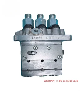
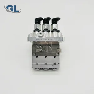
Fuel Injection Pump 104205-3072 16006-51010 104205-3071 104205-3070 16861-51010 Suitable for Kubota for Komatsu Engine 3D67E-1A for Kubota TG1860 ZD323 B7300HSD Tractors BX1860 BX2360 BX2380
Generic 🔥Part Name:Fuel Injection Pump || 🔥Part Number:104205-3072 16006-51010 104205-3071 104205-3070 16861-51010 || 🔥Application:Suitable for Kubota for Komatsu Engine 3D67E-1A for Kubota TG1860 ZD323 B7300HSD Tractors BX1860 BX2360 BX2380 || 🔥Attention: If you are unsure if the product is suitable for your machine model. In order not to delay your use of the parts, please provide your engine nameplate or serial number and part number, and we will help you confirm if it is suitable. To avoid unnecessary returns, please carefully check the product image and part number to ensure that it is the product you want. Thank you for your support and understanding! || 🔥Tip: If you need any other parts, please contact us - we are a professional sales team and have many products to offer to you. Many buyers are very satisfied with our service. You can get first-class products and high-quality services from us, believe me, you will have a pleasant shopping experience here.
Generic 🔥Part Name:Fuel Injection Pump || 🔥Part Number:104205-3072 16006-51010 104205-3071 104205-3070 16861-51010 || 🔥Application:Suitable for Kubota for Komatsu Engine 3D67E-1A for Kubota TG1860 ZD323 B7300HSD Tractors BX1860 BX2360 BX2380 || 🔥Attention: If you are unsure if the product is suitable for your machine model. In order not to delay your use of the parts, please provide your engine nameplate or serial number and part number, and we will help you confirm if it is suitable. To avoid unnecessary returns, please carefully check the product image and part number to ensure that it is the product you want. Thank you for your support and understanding! || 🔥Tip: If you need any other parts, please contact us - we are a professional sales team and have many products to offer to you. Many buyers are very satisfied with our service. You can get first-class products and high-quality services from us, believe me, you will have a pleasant shopping experience here.

Fuel Pump, Compatible with Kubota D722 Engine ZD18 ZD21, B7300HSD BX1830D 16861-51011 104205-3070 9410617319 Excavator Parts(16861-51011)
Adfghjk Compatible with Kubota D722 Engines: Fuel Pump 16861-51011, OEM-spec calibrated for ZD21/BX1830D tractors. || Industrial-Grade Pressure: Dual-plunger design achieves 300kPa±1.5% stable pressure with 18% efficiency boost. || Mud-Proof Construction: Cast aluminum housing and chrome-plated sleeves pass 1500hr mud tests, 3x lifespan. || Extreme Climate Certified: Operates at -20℃~+85℃ with ≤0.8% pressure variance. || 1-Hour Tool-Free Install: SAE J2044 flange with D722-specific anti-corrosion bolts.
Adfghjk Compatible with Kubota D722 Engines: Fuel Pump 16861-51011, OEM-spec calibrated for ZD21/BX1830D tractors. || Industrial-Grade Pressure: Dual-plunger design achieves 300kPa±1.5% stable pressure with 18% efficiency boost. || Mud-Proof Construction: Cast aluminum housing and chrome-plated sleeves pass 1500hr mud tests, 3x lifespan. || Extreme Climate Certified: Operates at -20℃~+85℃ with ≤0.8% pressure variance. || 1-Hour Tool-Free Install: SAE J2044 flange with D722-specific anti-corrosion bolts.

WZCNLXLX Fuel Pump 16861-51011 104205-3070 9410617319 For Kubota D722 ZD18 ZD21 BX1830D
WZCNLXLX Item Name:Fuel Injection Pump || Item Number:16861-51011 104205-3070 9410617319 1686151011 1042053070 || Application:For Kubota D722 Engine ZD18 ZD21 B7300HSD BX1830D || Note: If you are unsure if the product is suitable.In order not to delay your use of the parts, please provide your engine nameplate or serial number and part number, and we will help you confirm if it is suitable. To avoid unnecessary returns, please check the product image and part number to ensure it is the product you want. || Tip: Please contact us - we are a professional sales team and we have many products to offer to you. Many buyers are very satisfied with our service. You can get first-class products and high-quality services from us, believe me, you will have a pleasant shopping experience here.
WZCNLXLX Item Name:Fuel Injection Pump || Item Number:16861-51011 104205-3070 9410617319 1686151011 1042053070 || Application:For Kubota D722 Engine ZD18 ZD21 B7300HSD BX1830D || Note: If you are unsure if the product is suitable.In order not to delay your use of the parts, please provide your engine nameplate or serial number and part number, and we will help you confirm if it is suitable. To avoid unnecessary returns, please check the product image and part number to ensure it is the product you want. || Tip: Please contact us - we are a professional sales team and we have many products to offer to you. Many buyers are very satisfied with our service. You can get first-class products and high-quality services from us, believe me, you will have a pleasant shopping experience here.
You can express buy:
USD 546.74
14-06-2025
14-06-2025
ZQYM Diesel engien system parts 16006-51010 16006-51012 104205-3072 104205-3071 104205-3070 Fuel Injection Pump for Kubota
USD 458.55
01-07-2025
01-07-2025
China Made New Fuel Injection Pump 16861-51011 104205-3070 9410617319 compatible for Kubota D722
Images:
USD 458.55

[01-Jul-2025]
Components :
| 0. | INJECTION-PUMP ASSEMBLY | 104205-3070 |
| 1. | _ | |
| 2. | FUEL INJECTION PUMP | |
| 3. | NUMBER PLATE | |
| 4. | _ | |
| 5. | CAPSULE | |
| 6. | ADJUSTING DEVICE | |
| 7. | NOZZLE AND HOLDER ASSY | |
| 8. | Nozzle and Holder | |
| 9. | Open Pre:MPa(Kqf/cm2) | |
| 10. | NOZZLE-HOLDER | |
| 11. | NOZZLE |
Scheme ###:
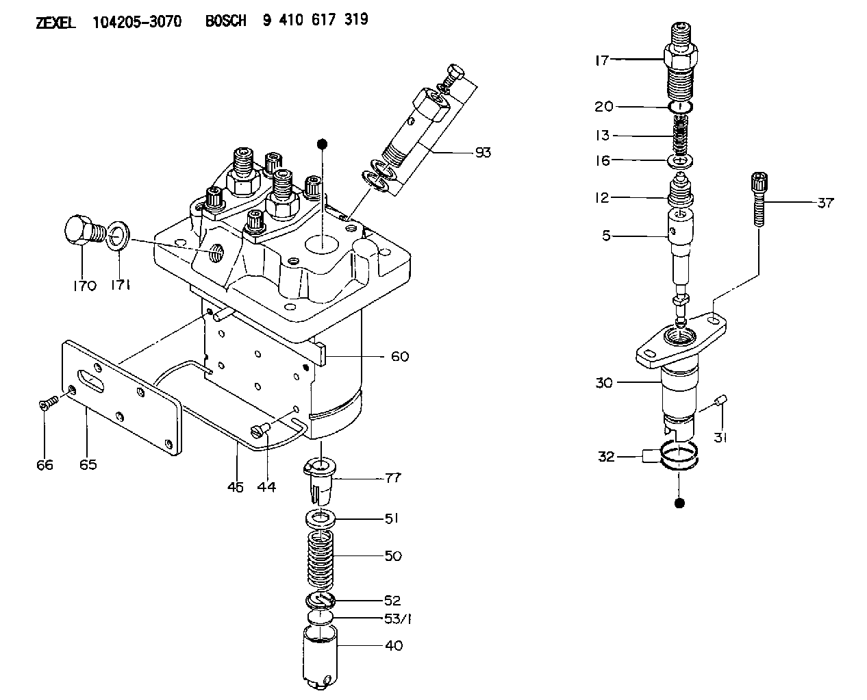
| 5. | [3] | 140154-1720 | PLUNGER-AND-BARREL ASSY |
| 12. | [3] | 140110-4420 | DELIVERY-VALVE ASSEMBLY |
| 13. | [3] | 140112-2800 | COMPRESSION SPRING |
| 16. | [3] | 140115-2200 | GASKET D12.8&8.6T0.5 |
| 17. | [3] | 140116-7820 | FITTING |
| 20. | [3] | 016550-1220 | O-RING |
| 30. | [3] | 140131-0020 | FLANGE BUSHING |
| 31. | [3] | 140271-0000 | BEARING PIN |
| 32. | [6] | 016550-1620 | O-RING |
| 37. | [6] | 140124-0100 | FLAT-HEAD SCREW |
| 40. | [3] | 140200-2320 | TAPPET |
| 44. | [3] | 140212-0300 | BEARING PIN |
| 45. | [1] | 140213-0900 | LOCKING WASHER |
| 50. | [3] | 140215-2000 | COMPRESSION SPRING |
| 51. | [3] | 140216-1300 | SLOTTED WASHER |
| 52. | [3] | 140254-2900 | SLOTTED WASHER |
| 53/1. | [1] | 140254-1400 | PLATE T1.80 |
| 53/1. | [1] | 140254-1500 | PLATE T1.85 |
| 53/1. | [1] | 140254-1600 | PLATE T1.90 |
| 53/1. | [1] | 140254-1700 | PLATE T1.95 |
| 53/1. | [1] | 140254-1800 | PLATE T2.00 |
| 53/1. | [1] | 140254-1900 | PLATE T2.05 |
| 53/1. | [1] | 140254-2000 | PLATE T2.10 |
| 53/1. | [1] | 140254-2100 | PLATE T2.15 |
| 53/1. | [1] | 140254-2200 | PLATE T2.20 |
| 53/1. | [1] | 140254-2300 | PLATE T2.25 |
| 53/1. | [1] | 140254-2400 | PLATE T2.30 |
| 53/1. | [1] | 140254-2500 | PLATE T2.35 |
| 53/1. | [1] | 140254-2600 | PLATE T2.40 |
| 53/1. | [1] | 140254-2700 | PLATE T2.45 |
| 53/1. | [1] | 140254-2800 | PLATE T2.50 |
| 53/1. | [1] | 140254-3100 | PLATE T1.825 |
| 53/1. | [1] | 140254-3200 | PLATE T1.875 |
| 53/1. | [1] | 140254-3300 | PLATE T1.925 |
| 53/1. | [1] | 140254-3400 | PLATE T1.975 |
| 53/1. | [1] | 140254-3500 | PLATE T2.025 |
| 53/1. | [1] | 140254-3600 | PLATE T2.075 |
| 53/1. | [1] | 140254-3700 | PLATE T2.125 |
| 53/1. | [1] | 140254-3800 | PLATE T2.175 |
| 53/1. | [1] | 140254-3900 | PLATE T2.225 |
| 53/1. | [1] | 140254-4000 | PLATE T2.275 |
| 53/1. | [1] | 140254-4100 | PLATE T2.325 |
| 53/1. | [1] | 140254-4200 | PLATE T2.375 |
| 53/1. | [1] | 140254-4300 | PLATE T2.425 |
| 53/1. | [1] | 140254-4400 | PLATE T2.475 |
| 53/1. | [1] | 140254-4500 | PLATE T2.525 |
| 60. | [1] | 140243-3720 | CONTROL RACK |
| 65. | [1] | 140262-0500 | PLATE |
| 66. | [4] | 140252-0000 | FLAT-HEAD SCREW |
| 77. | [3] | 140241-4020 | CONTROL SLEEVE |
| 93. | [1] | 140402-3020 | EYE BOLT |
| 170. | [1] | 140405-0100 | CAPSULE |
| 171. | [1] | 026510-1340 | GASKET D13.4&10.2T1 |
Cross reference number
Zexel num
Bosch num
Firm num
Name
Information:
2. Turn the crankshaft until two pistons are at bottom center.3. Remove bolts (1) and the bearing caps. Push the rods and pistons up until the rings are out of the cylinder liners. 4. Remove pistons (2) and connecting rods from the cylinder liners.5. Do Steps 1 through 4 for the remainder of the pistons and connecting rods.Install Pistons And Connecting Rod Assemblies
1. Put clean engine oil on piston rings, connecting rod bearings and cylinder liners. 2. Use tool (A), and install piston (2) and the connecting rod in the cylinder liner. Be sure the number on the tab groove side of the connecting rod is on the opposite side from the camshaft.3. Install the bearing cap on the connecting rod with the number on the side of the bearing cap on the same side and same number as on the connecting rod.4. Put 2P2506 Thread Lubricant on the threads of the bolts. Install the bolts, and tighten them to a torque 90 8 N m (65 6 lb ft.). Put a mark on the bolts and tighten the bolts an additional 90 5°.5. Do Steps 1 through 4 for the remainder of the pistons and connecting rods.End By:a. install oil pumpb. install cylinder head assemblyDisassemble And Assemble Pistons And Connecting Rod Assemblies
Start By:a. remove pistons and connecting rod assemblies 1. Remove bearings (2) from the connecting rod and connecting rod cap.2. Remove retainer ring (1) and tool (A).3. Remove pin (2) and connecting rod (4) from the piston. 4. Remove piston rings (5) from the piston with tool (B). Clean the piston ring grooves on the pistons with an acceptable ring groove cleaning tool. See, Use Of Piston Pin Bearing Removal And Installation Tools, Special Instructions, Form No. SMHS7295.5. Heat connecting rod (4) in an oven to a temperature of 177° to 260° C (350° to 500° F). Never use a direct flame or heat a connecting rod. 6. Put connecting rod (4) in position on the base plate of tooling (C). Put a new rod pin bearing (6) on the adapter of tooling (C). The old bearing is pushed out by tooling (C) as the new ring is installed.7. Use tooling (C) to push the new bearing into the connecting rod until the push adapter of tooling (C) make full contact with the connecting rod surface.8. Use a pin boring machine to make the rod pin bearing the correct size. The bore in the new rod pin bearing must be 50.830 0.008 mm (2.0012 .0003 in.).9. Check the clearance between the ends of the piston rings. See the topic, Pistons and Rings in the Specifications manual.10. Install the oil ring spring in the oil ring groove of the piston. The oil ring is to be installed over the spring with the oil ring end gap 180° from the oil ring spring joint.11. Install the oil ring on the piston with tool (B).12. Install the second (intermediate) piston ring with the side