Information fuel-injection pump
BOSCH
9 410 618 408
9410618408
ZEXEL
104205-2091
1042052091
KUBOTA
1E11051011
1e11051011
Rating:
Compare Prices: .
As an associate, we earn commssions on qualifying purchases through the links below

Fuel Injection Pump Compatible With Kubota 1E110-51010 1E110-51011 104205-2090 9410618354 Excavator Engine Replacement Parts
YERCBX Integrated design: Compact structure, small space occupation, and convenient for vehicle installation and layout. || Easy maintenance: The design is reasonable, and daily inspection and maintenance operations are simple, saving time || Lightweight design: Reducing its own weight helps to achieve overall lightweighting of the vehicle || The installation interface design is convenient for installation and saves installation time. || Modular design: Facilitates maintenance and replacement of damaged parts, reducing maintenance costs.
YERCBX Integrated design: Compact structure, small space occupation, and convenient for vehicle installation and layout. || Easy maintenance: The design is reasonable, and daily inspection and maintenance operations are simple, saving time || Lightweight design: Reducing its own weight helps to achieve overall lightweighting of the vehicle || The installation interface design is convenient for installation and saves installation time. || Modular design: Facilitates maintenance and replacement of damaged parts, reducing maintenance costs.

Fuel Injection Pump Compatible For Kubota 1E110-51010 1E110-51011 104205-2090 9410618354 Excavator Engine Replacement Parts
TBEFQVAW Lightweight design: effectively reduces vehicle load, improves fuel economy, and facilitates installation and handling || Multi specification adaptation: providing multiple flow specifications and models to meet the needs of different displacement engines || Adaptive installation: Standardized interface design, compatible with 95% of mainstream engine models, no need for complex modifications || Anti corrosion coating: The surface of key components is covered with anti-corrosion coating, which is not afraid of humid coastal environments and harsh weather conditions || Fuel Injection Pump Compatible For Kubota 1E110-51010 1E110-51011 104205-2090 9410618354 Excavator Engine Replacement Parts
TBEFQVAW Lightweight design: effectively reduces vehicle load, improves fuel economy, and facilitates installation and handling || Multi specification adaptation: providing multiple flow specifications and models to meet the needs of different displacement engines || Adaptive installation: Standardized interface design, compatible with 95% of mainstream engine models, no need for complex modifications || Anti corrosion coating: The surface of key components is covered with anti-corrosion coating, which is not afraid of humid coastal environments and harsh weather conditions || Fuel Injection Pump Compatible For Kubota 1E110-51010 1E110-51011 104205-2090 9410618354 Excavator Engine Replacement Parts

1E110-51010 1E110-51011 104205-2090 Fuel Injection Pump for Kubota Z482 Z482-E2B Engine BX1500D GR1600EC2 T1600H Tractors GZD15 KC120H GL6000 GL7000 J106 Generator
HIRINTOL 🔸Replace Part Number: 1E110-51010, 1E110-51011, 104205-2090, 1E11051010, 1E11051011, 1042052090 || 🔸Engine Model: for Kubota Engine Z482, Z482-BBS, Z482-E2B-DGDE-4 || 🔸Compatible Model: for Kubota Generator GL6000, GL7000, J106, GL6000-AUS, GL6000-STD(50HZ), GL7000-STD(60Hz), J106-AUS Fit For Kubota Tractor:BX1500D, GR1600EC2, T1600H, T1600H-EUROPE, T1600H-G || 🔸Compatible Model: for Kubota Tractor BX1500D, GR1600EC2, T1600H, T1600H-EUROPE, T1600H-G; Kubota Zero-turn Mower GZD15, GZD15-HD, GZD15-IIHD, GZD15-IILD, GZD15-LD; for Kubota Track Carrier KC120H, KC120HC || 🔸Efficient And Stable: Using advanced technology, it can provide efficient and stable fuel supply to ensure the normal operation of the vehicle.
HIRINTOL 🔸Replace Part Number: 1E110-51010, 1E110-51011, 104205-2090, 1E11051010, 1E11051011, 1042052090 || 🔸Engine Model: for Kubota Engine Z482, Z482-BBS, Z482-E2B-DGDE-4 || 🔸Compatible Model: for Kubota Generator GL6000, GL7000, J106, GL6000-AUS, GL6000-STD(50HZ), GL7000-STD(60Hz), J106-AUS Fit For Kubota Tractor:BX1500D, GR1600EC2, T1600H, T1600H-EUROPE, T1600H-G || 🔸Compatible Model: for Kubota Tractor BX1500D, GR1600EC2, T1600H, T1600H-EUROPE, T1600H-G; Kubota Zero-turn Mower GZD15, GZD15-HD, GZD15-IIHD, GZD15-IILD, GZD15-LD; for Kubota Track Carrier KC120H, KC120HC || 🔸Efficient And Stable: Using advanced technology, it can provide efficient and stable fuel supply to ensure the normal operation of the vehicle.
You can express buy:
USD 269.57
01-07-2025
01-07-2025
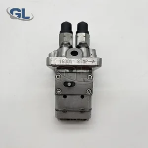
China Made New Fuel Injection Pump 1E110-51011 104205-2090 9410618354 compatible for Kubota Z482
Components :
| 0. | INJECTION-PUMP ASSEMBLY | 104205-2091 |
| 1. | _ | |
| 2. | FUEL INJECTION PUMP | |
| 3. | NUMBER PLATE | |
| 4. | _ | |
| 5. | CAPSULE | |
| 6. | ADJUSTING DEVICE | |
| 7. | NOZZLE AND HOLDER ASSY | |
| 8. | Nozzle and Holder | |
| 9. | Open Pre:MPa(Kqf/cm2) | |
| 10. | NOZZLE-HOLDER | |
| 11. | NOZZLE |
Scheme ###:
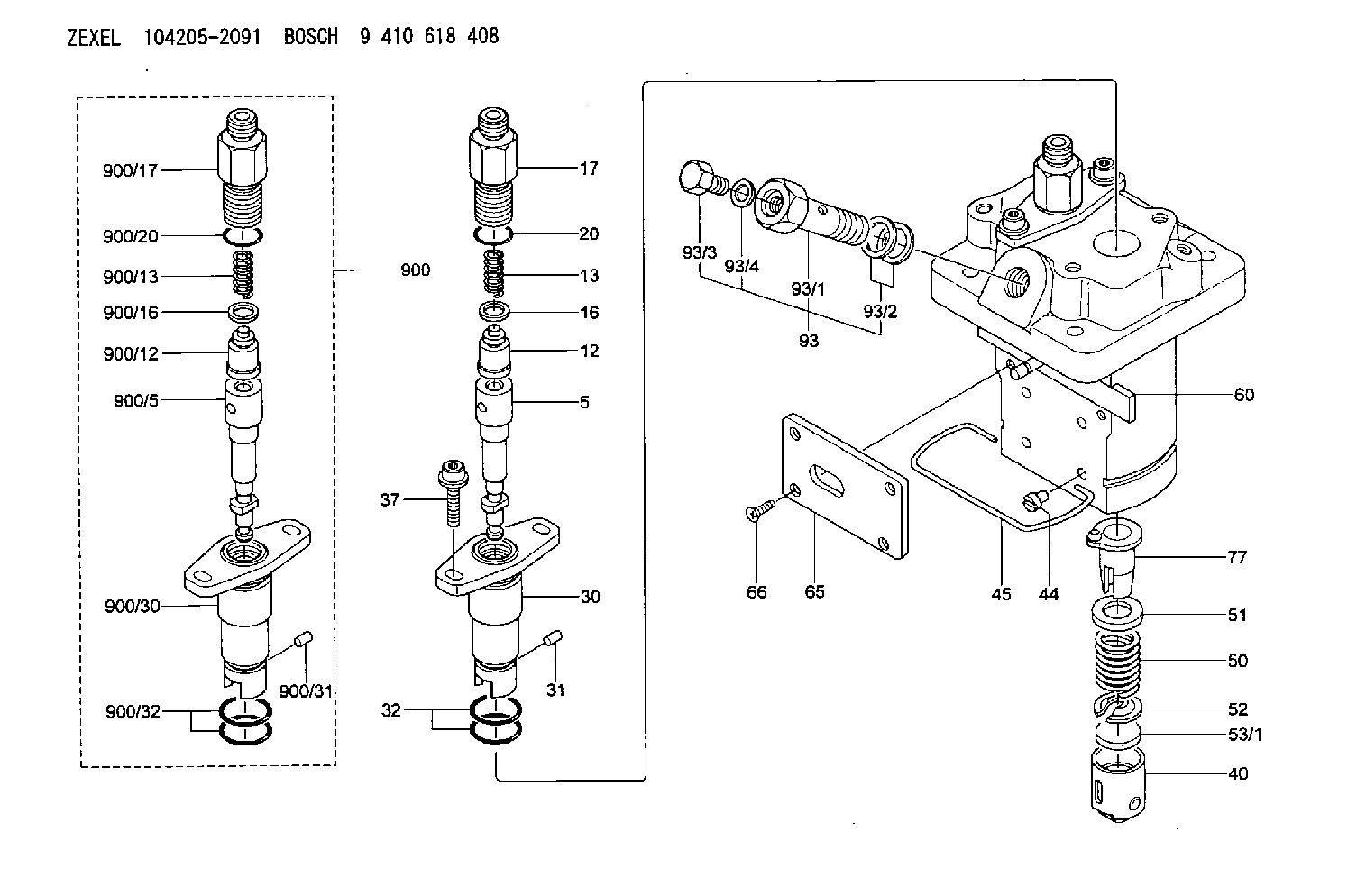
| 5. | [2] | 140154-1720 | PLUNGER-AND-BARREL ASSY |
| 12. | [2] | 140110-4420 | DELIVERY-VALVE ASSEMBLY |
| 13. | [2] | 140112-2800 | COMPRESSION SPRING |
| 16. | [2] | 140115-2200 | GASKET D12.8&8.6T0.5 |
| 17. | [2] | 140116-7820 | FITTING |
| 20. | [2] | 140118-0500 | O-RING |
| 30. | [2] | 140131-0021 | FLANGE BUSHING |
| 31. | [2] | 140271-0000 | BEARING PIN |
| 32. | [4] | 140118-0400 | O-RING |
| 37. | [4] | 140124-0100 | FLAT-HEAD SCREW |
| 40. | [2] | 140200-2320 | TAPPET |
| 44. | [2] | 140212-0300 | BEARING PIN |
| 45. | [1] | 140213-0800 | LOCKING WASHER |
| 50. | [2] | 140215-2000 | COMPRESSION SPRING |
| 51. | [2] | 140216-1300 | SLOTTED WASHER |
| 52. | [2] | 140254-2900 | SLOTTED WASHER |
| 53/1. | [1] | 140254-1400 | PLATE T1.80 |
| 53/1. | [1] | 140254-1500 | PLATE T1.85 |
| 53/1. | [1] | 140254-1600 | PLATE T1.90 |
| 53/1. | [1] | 140254-1700 | PLATE T1.95 |
| 53/1. | [1] | 140254-1800 | PLATE T2.00 |
| 53/1. | [1] | 140254-1900 | PLATE T2.05 |
| 53/1. | [1] | 140254-2000 | PLATE T2.10 |
| 53/1. | [1] | 140254-2100 | PLATE T2.15 |
| 53/1. | [1] | 140254-2200 | PLATE T2.20 |
| 53/1. | [1] | 140254-2300 | PLATE T2.25 |
| 53/1. | [1] | 140254-2400 | PLATE T2.30 |
| 53/1. | [1] | 140254-2500 | PLATE T2.35 |
| 53/1. | [1] | 140254-2600 | PLATE T2.40 |
| 53/1. | [1] | 140254-2700 | PLATE T2.45 |
| 53/1. | [1] | 140254-2800 | PLATE T2.50 |
| 53/1. | [1] | 140254-3100 | PLATE T1.825 |
| 53/1. | [1] | 140254-3200 | PLATE T1.875 |
| 53/1. | [1] | 140254-3300 | PLATE T1.925 |
| 53/1. | [1] | 140254-3400 | PLATE T1.975 |
| 53/1. | [1] | 140254-3500 | PLATE T2.025 |
| 53/1. | [1] | 140254-3600 | PLATE T2.075 |
| 53/1. | [1] | 140254-3700 | PLATE T2.125 |
| 53/1. | [1] | 140254-3800 | PLATE T2.175 |
| 53/1. | [1] | 140254-3900 | PLATE T2.225 |
| 53/1. | [1] | 140254-4000 | PLATE T2.275 |
| 53/1. | [1] | 140254-4100 | PLATE T2.325 |
| 53/1. | [1] | 140254-4200 | PLATE T2.375 |
| 53/1. | [1] | 140254-4300 | PLATE T2.425 |
| 53/1. | [1] | 140254-4400 | PLATE T2.475 |
| 53/1. | [1] | 140254-4500 | PLATE T2.525 |
| 60. | [1] | 140243-7720 | CONTROL ROD |
| 65. | [1] | 140262-1600 | PLATE |
| 66. | [4] | 140252-0001 | FLAT-HEAD SCREW |
| 77. | [2] | 140241-4021 | CONTROL SLEEVE |
| 93. | [1] | 140402-3020 | EYE BOLT |
| 93/1. | [1] | 140402-3000 | EYE BOLT |
| 93/2. | [2] | 026510-1340 | GASKET D13.4&10.2T1 |
| 93/3. | [1] | 140420-2400 | BLEEDER SCREW |
| 93/4. | [1] | 026506-1040 | GASKET D9.9&6.2T1 |
| 900. | [2] | 140191-0720 | PLUNGER-AND-BARREL ASSY |
| 900/5. | [1] | 140154-1720 | PLUNGER-AND-BARREL ASSY |
| 900/12. | [1] | 140110-4420 | DELIVERY-VALVE ASSEMBLY |
| 900/13. | [1] | 140112-2800 | COMPRESSION SPRING |
| 900/16. | [1] | 140115-2200 | GASKET D12.8&8.6T0.5 |
| 900/17. | [1] | 140116-7820 | FITTING |
| 900/20. | [1] | 140118-0500 | O-RING |
| 900/30. | [1] | 140131-0021 | FLANGE BUSHING |
| 900/31. | [1] | 140271-0000 | BEARING PIN |
| 900/32. | [2] | 140118-0400 | O-RING |
Cross reference number
Zexel num
Bosch num
Firm num
Name
Information:
Start By:a. remove timing gear coverb. remove fuel injection pump housing and rack actuator package 1. Remove four bolts (2) plate (3) and idler gear (1). 2. If the camshaft is not going to be removed, use tooling (A) to remove camshaft gear (4).
Do not turn the crankshaft with the camshaft gear removed. Damage can be caused to the pistons and valves, or both.
3. Remove bolts (5) that hold timing gear plate (6) to the cylinder block.4. Remove timing gear plate (6). 5. Use tooling (B) to remove the bearing from the idler gear. The following steps are for the installation of the timing gears and plate.6. Install a new gasket in the timing gear plate.7. Put timing gear plate (6) in position on the cylinder block, and install the bolts that hold the timing gear plate to the cylinder block.8. Heat camshaft gear (4) to a maximum temperature of 315° C (600° F), and install it on the camshaft.9. Use tooling (B), and install the bearing in the idler gear. Set the gear to the front face, (face with timing marks). Drive the bearing from the rear face toward the front face of the gear. Install the bearing to a depth of 1.5 0.5 mm (.06 .02 in.) below the rear face of the idler gear.10. Install the idler gear, plate and bolts. Be sure No. 1 cylinder is at top center on the compression stroke. Install the idler gear so "V" mark (7) on the idler gear is in alignment with the "V" mark on the crankshaft gear. "K" marks (8) of the camshaft gear can be seen at the outer edges of the idler gear.End By:a. install fuel injection pump housing and rack actuator packageb. install timing gear cover