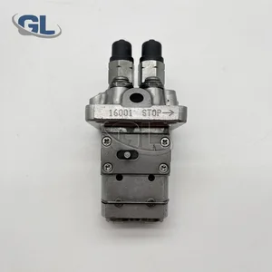
Information fuel-injection pump
BOSCH
9 410 618 354
9410618354
ZEXEL
104205-2090
1042052090
KUBOTA
1E11051011
1e11051011

Rating:
Compare Prices: .
As an associate, we earn commssions on qualifying purchases through the links below

Fuel Injection Pump Compatible With Kubota 1E110-51010 1E110-51011 104205-2090 9410618354 Excavator Engine Replacement Parts
YERCBX Integrated design: Compact structure, small space occupation, and convenient for vehicle installation and layout. || Easy maintenance: The design is reasonable, and daily inspection and maintenance operations are simple, saving time || Lightweight design: Reducing its own weight helps to achieve overall lightweighting of the vehicle || The installation interface design is convenient for installation and saves installation time. || Modular design: Facilitates maintenance and replacement of damaged parts, reducing maintenance costs.
YERCBX Integrated design: Compact structure, small space occupation, and convenient for vehicle installation and layout. || Easy maintenance: The design is reasonable, and daily inspection and maintenance operations are simple, saving time || Lightweight design: Reducing its own weight helps to achieve overall lightweighting of the vehicle || The installation interface design is convenient for installation and saves installation time. || Modular design: Facilitates maintenance and replacement of damaged parts, reducing maintenance costs.

Fuel Injection Pump Compatible For Kubota 1E110-51010 1E110-51011 104205-2090 9410618354 Excavator Engine Replacement Parts
TBEFQVAW Lightweight design: effectively reduces vehicle load, improves fuel economy, and facilitates installation and handling || Multi specification adaptation: providing multiple flow specifications and models to meet the needs of different displacement engines || Adaptive installation: Standardized interface design, compatible with 95% of mainstream engine models, no need for complex modifications || Anti corrosion coating: The surface of key components is covered with anti-corrosion coating, which is not afraid of humid coastal environments and harsh weather conditions || Fuel Injection Pump Compatible For Kubota 1E110-51010 1E110-51011 104205-2090 9410618354 Excavator Engine Replacement Parts
TBEFQVAW Lightweight design: effectively reduces vehicle load, improves fuel economy, and facilitates installation and handling || Multi specification adaptation: providing multiple flow specifications and models to meet the needs of different displacement engines || Adaptive installation: Standardized interface design, compatible with 95% of mainstream engine models, no need for complex modifications || Anti corrosion coating: The surface of key components is covered with anti-corrosion coating, which is not afraid of humid coastal environments and harsh weather conditions || Fuel Injection Pump Compatible For Kubota 1E110-51010 1E110-51011 104205-2090 9410618354 Excavator Engine Replacement Parts
You can express buy:
USD 269.57
01-07-2025
01-07-2025
China Made New Fuel Injection Pump 1E110-51011 104205-2090 9410618354 compatible for Kubota Z482
Components :
| 0. | INJECTION-PUMP ASSEMBLY | 104205-2090 |
| 1. | _ | |
| 2. | FUEL INJECTION PUMP | |
| 3. | NUMBER PLATE | |
| 4. | _ | |
| 5. | CAPSULE | |
| 6. | ADJUSTING DEVICE | |
| 7. | NOZZLE AND HOLDER ASSY | |
| 8. | Nozzle and Holder | |
| 9. | Open Pre:MPa(Kqf/cm2) | |
| 10. | NOZZLE-HOLDER | |
| 11. | NOZZLE |
Scheme ###:
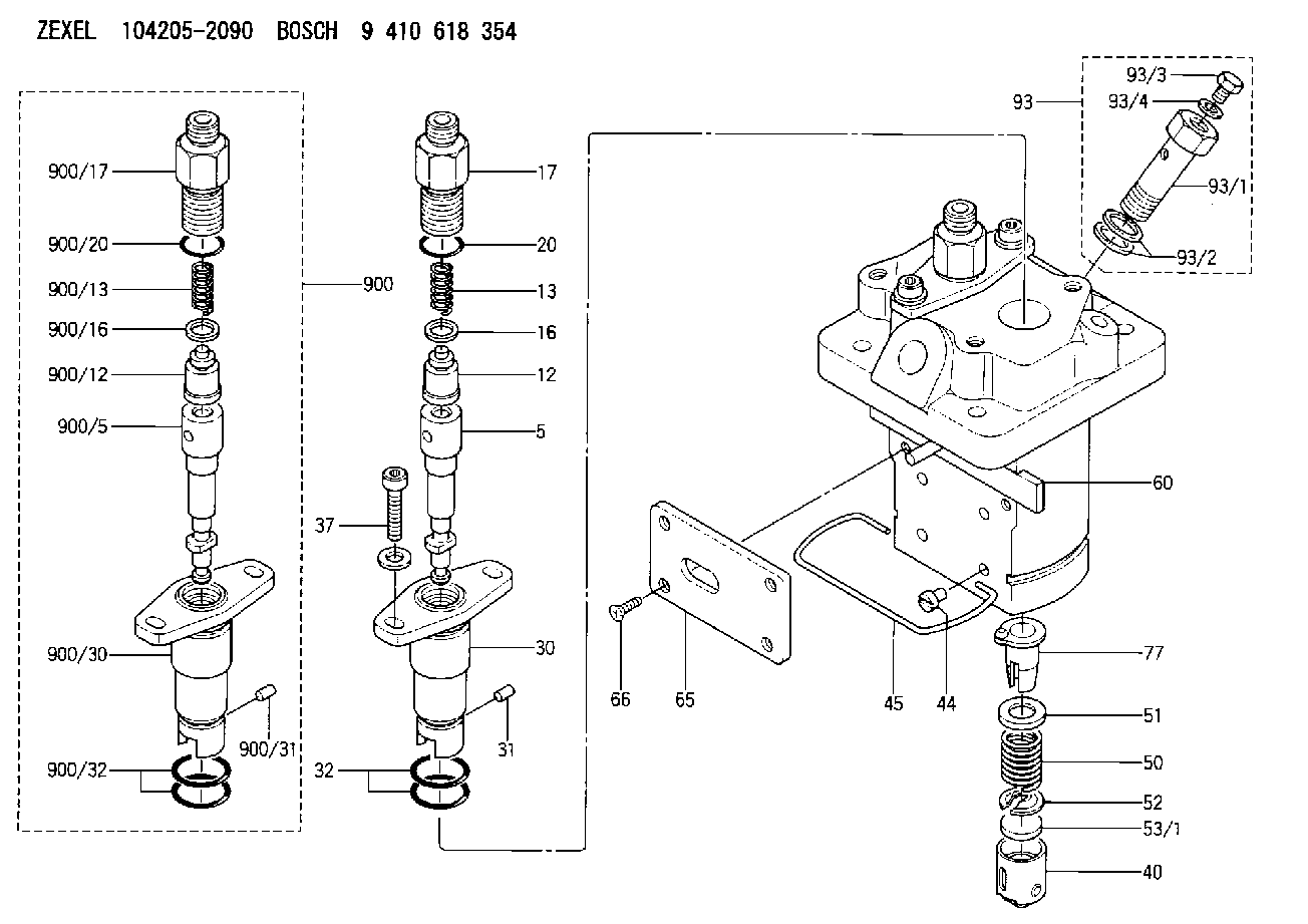
| 5. | [2] | 140154-1720 | PLUNGER-AND-BARREL ASSY |
| 12. | [2] | 140110-4420 | DELIVERY-VALVE ASSEMBLY |
| 13. | [2] | 140112-2800 | COMPRESSION SPRING |
| 16. | [2] | 140115-2200 | GASKET D12.8&8.6T0.5 |
| 17. | [2] | 140116-7820 | FITTING |
| 20. | [2] | 140118-0500 | O-RING |
| 30. | [2] | 140131-0021 | FLANGE BUSHING |
| 31. | [2] | 140271-0000 | BEARING PIN |
| 32. | [4] | 140118-0400 | O-RING |
| 37. | [4] | 140124-0100 | FLAT-HEAD SCREW |
| 40. | [2] | 140200-2320 | TAPPET |
| 44. | [2] | 140212-0300 | BEARING PIN |
| 45. | [1] | 140213-0800 | LOCKING WASHER |
| 50. | [2] | 140215-2000 | COMPRESSION SPRING |
| 51. | [2] | 140216-1300 | SLOTTED WASHER |
| 52. | [2] | 140254-2900 | SLOTTED WASHER |
| 53/1. | [1] | 140254-1400 | PLATE T1.80 |
| 53/1. | [1] | 140254-1500 | PLATE T1.85 |
| 53/1. | [1] | 140254-1600 | PLATE T1.90 |
| 53/1. | [1] | 140254-1700 | PLATE T1.95 |
| 53/1. | [1] | 140254-1800 | PLATE T2.00 |
| 53/1. | [1] | 140254-1900 | PLATE T2.05 |
| 53/1. | [1] | 140254-2000 | PLATE T2.10 |
| 53/1. | [1] | 140254-2100 | PLATE T2.15 |
| 53/1. | [1] | 140254-2200 | PLATE T2.20 |
| 53/1. | [1] | 140254-2300 | PLATE T2.25 |
| 53/1. | [1] | 140254-2400 | PLATE T2.30 |
| 53/1. | [1] | 140254-2500 | PLATE T2.35 |
| 53/1. | [1] | 140254-2600 | PLATE T2.40 |
| 53/1. | [1] | 140254-2700 | PLATE T2.45 |
| 53/1. | [1] | 140254-2800 | PLATE T2.50 |
| 53/1. | [1] | 140254-3100 | PLATE T1.825 |
| 53/1. | [1] | 140254-3200 | PLATE T1.875 |
| 53/1. | [1] | 140254-3300 | PLATE T1.925 |
| 53/1. | [1] | 140254-3400 | PLATE T1.975 |
| 53/1. | [1] | 140254-3500 | PLATE T2.025 |
| 53/1. | [1] | 140254-3600 | PLATE T2.075 |
| 53/1. | [1] | 140254-3700 | PLATE T2.125 |
| 53/1. | [1] | 140254-3800 | PLATE T2.175 |
| 53/1. | [1] | 140254-3900 | PLATE T2.225 |
| 53/1. | [1] | 140254-4000 | PLATE T2.275 |
| 53/1. | [1] | 140254-4100 | PLATE T2.325 |
| 53/1. | [1] | 140254-4200 | PLATE T2.375 |
| 53/1. | [1] | 140254-4300 | PLATE T2.425 |
| 53/1. | [1] | 140254-4400 | PLATE T2.475 |
| 53/1. | [1] | 140254-4500 | PLATE T2.525 |
| 60. | [1] | 140243-7720 | CONTROL ROD |
| 65. | [1] | 140262-1600 | PLATE |
| 66. | [4] | 140252-0001 | FLAT-HEAD SCREW |
| 77. | [2] | 140241-4021 | CONTROL SLEEVE |
| 93. | [1] | 140402-3020 | EYE BOLT |
| 93/1. | [1] | 140402-3000 | EYE BOLT |
| 93/2. | [2] | 026510-1340 | GASKET D13.4&10.2T1 |
| 93/3. | [1] | 140420-2400 | BLEEDER SCREW |
| 93/4. | [1] | 026506-1040 | GASKET D9.9&6.2T1 |
| 900. | [2] | 140191-0720 | PLUNGER-AND-BARREL ASSY |
| 900/5. | [1] | 140154-1720 | PLUNGER-AND-BARREL ASSY |
| 900/12. | [1] | 140110-4420 | DELIVERY-VALVE ASSEMBLY |
| 900/13. | [1] | 140112-2800 | COMPRESSION SPRING |
| 900/16. | [1] | 140115-2200 | GASKET D12.8&8.6T0.5 |
| 900/17. | [1] | 140116-7820 | FITTING |
| 900/20. | [1] | 140118-0500 | O-RING |
| 900/30. | [1] | 140131-0021 | FLANGE BUSHING |
| 900/31. | [1] | 140271-0000 | BEARING PIN |
| 900/32. | [2] | 140118-0400 | O-RING |
Cross reference number
Zexel num
Bosch num
Firm num
Name
1E11051011 KUBOTA
FUEL-INJECTION PUMP
* K 23MB FUEL INJECTION PUMP PFR-2MD PFR
* K 23MB FUEL INJECTION PUMP PFR-2MD PFR
Information:
1. Loosen two bolts (2) and two nuts (3). Remove bolt (1), and remove fan drive belts (4). 2. Remove the nuts and bolts that hold the fan drive in place. Remove fan drive (5). The following steps are for installation of the fan drive.3. Put fan drive (5) in position on the timing gear cover.4. Install bolts (2) and nuts (3) loosely. Make a replacement of the belts as a set only.5. Install fan bolts (4). Install bolt (1). Make an adjustment to the belt tension with tool (A). Measure the belt farthest away from the engine. Tighten new belts to a gauge indication of 120 5. After the engine is operated at high idle for a minimum of 30 minutes, make another adjustment to the belt tension. The correct tension for used belts is a gauge indication of 90 10.6. Tighten bolts (2) and nuts (3) that hold the fan drive in place.Disassemble Fan Drive
Start By:a. remove fan drive This is a typical later model fan drive. 1. Remove two bolts (2) that hold the fan adapter to the pulley.2. Remove fan adapter (1) from the pulley. 3. Remove bolts (3) and washer (4). Remove seal (5). 4. Remove pulley (8) from bracket (6).5. Remove bearing (10) and spacer (9) from the pulley. Remove spacer (7), seal (11) and bearing (12) from the pulley.Assemble Fan Drive
1. Install bearing (12) in the rear of the pulley (8). 2. Install lip-type seal (11) with tooling (A). The lip of the seal must be away from the bearing. Put 5P960 Multipurpose Type Grease on the lip of the seal.3. Install spacer (7) so the end with the taper is toward the inside of pulley (8).4. Install spacer (9) and bearing (4) in the front of the pulley. 5. Put seal (5) on the front of the pulley. Install the pulley on bracket (6). 6. Install washer (4) and bolts (3) that hold the pulley in position.7. Install the fan drive adapter on the pulley.8. Fill the fan drive with 5P960 Multipurpose Type Grease.End by:a. install fan drive