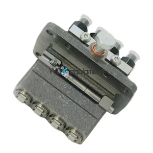
Information fuel-injection pump
BOSCH
9 410 617 316
9410617316
ZEXEL
104205-2061
1042052061
KUBOTA
1754851012
1754851012

Rating:
Compare Prices: .
As an associate, we earn commssions on qualifying purchases through the links below

1pc 17548-51012 104205-2060 9410617316 TYSTABPC
TYSTABPC
TYSTABPC
1pc 17548-51012 104205-2060 9410617316
HFJQZTLE
HFJQZTLE
Fuel Injection Pump Compatible For Kubota Z400 Z402 Z482 Z600 17548-51012 104205-2060 9410617316 Excavator Engine Replacement Parts
SDETASOQ Precise control: precise fuel injection, optimized combustion efficiency, reduced fuel consumption, and improved engine power output || Long lifespan and low maintenance: using high-strength wear-resistant alloy materials and corrosion-resistant coatings to reduce maintenance costs and downtime || Stable operation under all operating conditions: tested in extreme environments, continuously stable, and adaptable to various complex road and climate conditions || Silent and efficient operation: Adopting a noise reduction structure, it can maintain quietness even during high-speed operation, without interfering with the driving experience || Fuel Injection Pump Compatible For Kubota Z400 Z402 Z482 Z600 17548-51012 104205-2060 9410617316 Excavator Engine Replacement Parts
SDETASOQ Precise control: precise fuel injection, optimized combustion efficiency, reduced fuel consumption, and improved engine power output || Long lifespan and low maintenance: using high-strength wear-resistant alloy materials and corrosion-resistant coatings to reduce maintenance costs and downtime || Stable operation under all operating conditions: tested in extreme environments, continuously stable, and adaptable to various complex road and climate conditions || Silent and efficient operation: Adopting a noise reduction structure, it can maintain quietness even during high-speed operation, without interfering with the driving experience || Fuel Injection Pump Compatible For Kubota Z400 Z402 Z482 Z600 17548-51012 104205-2060 9410617316 Excavator Engine Replacement Parts
You can express buy:
USD 280.32
19-05-2025
19-05-2025
Fuel Injection Pump 17548-51012 104205-2060 For Kubota Z400 Z402 Z482 Z600 9410617316 Excavator Engine Parts
USD 268.8
18-06-2025
18-06-2025
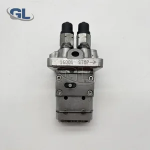
China Made New Fuel Injection Pump 17548-51012 104205-2061 9410618404 compatible for Kubota Z482
Images:
USD 268.8

[18-Jun-2025]
USD 269.38
[26-Jun-2025]
Components :
| 0. | INJECTION-PUMP ASSEMBLY | 104205-2061 |
| 1. | _ | |
| 2. | FUEL INJECTION PUMP | |
| 3. | NUMBER PLATE | |
| 4. | _ | |
| 5. | CAPSULE | |
| 6. | ADJUSTING DEVICE | |
| 7. | NOZZLE AND HOLDER ASSY | |
| 8. | Nozzle and Holder | |
| 9. | Open Pre:MPa(Kqf/cm2) | |
| 10. | NOZZLE-HOLDER | |
| 11. | NOZZLE |
Scheme ###:
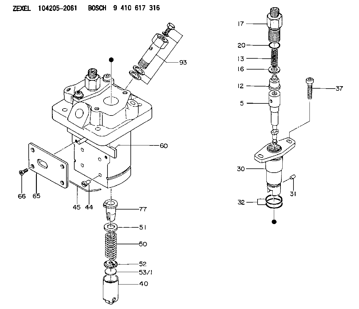
| 5. | [2] | 140154-7720 | PLUNGER-AND-BARREL ASSY |
| 12. | [2] | 140110-4420 | DELIVERY-VALVE ASSEMBLY |
| 13. | [2] | 140112-2800 | COMPRESSION SPRING |
| 16. | [2] | 140115-2200 | GASKET D12.8&8.6T0.5 |
| 17. | [2] | 140116-7820 | FITTING |
| 20. | [2] | 016550-1220 | O-RING |
| 30. | [2] | 140131-0021 | FLANGE BUSHING |
| 31. | [2] | 140271-0000 | BEARING PIN |
| 32. | [4] | 016550-1620 | O-RING |
| 37. | [4] | 140124-0100 | FLAT-HEAD SCREW |
| 40. | [2] | 140200-2320 | TAPPET |
| 44. | [2] | 140212-0300 | BEARING PIN |
| 45. | [1] | 140213-0800 | LOCKING WASHER |
| 50. | [2] | 140215-2000 | COMPRESSION SPRING |
| 51. | [2] | 140216-1300 | SLOTTED WASHER |
| 52. | [2] | 140254-2900 | SLOTTED WASHER |
| 53/1. | [1] | 140254-1400 | PLATE T1.80 |
| 53/1. | [1] | 140254-1500 | PLATE T1.85 |
| 53/1. | [1] | 140254-1600 | PLATE T1.90 |
| 53/1. | [1] | 140254-1700 | PLATE T1.95 |
| 53/1. | [1] | 140254-1800 | PLATE T2.00 |
| 53/1. | [1] | 140254-1900 | PLATE T2.05 |
| 53/1. | [1] | 140254-2000 | PLATE T2.10 |
| 53/1. | [1] | 140254-2100 | PLATE T2.15 |
| 53/1. | [1] | 140254-2200 | PLATE T2.20 |
| 53/1. | [1] | 140254-2300 | PLATE T2.25 |
| 53/1. | [1] | 140254-2400 | PLATE T2.30 |
| 53/1. | [1] | 140254-2500 | PLATE T2.35 |
| 53/1. | [1] | 140254-2600 | PLATE T2.40 |
| 53/1. | [1] | 140254-2700 | PLATE T2.45 |
| 53/1. | [1] | 140254-2800 | PLATE T2.50 |
| 53/1. | [1] | 140254-3100 | PLATE T1.825 |
| 53/1. | [1] | 140254-3200 | PLATE T1.875 |
| 53/1. | [1] | 140254-3300 | PLATE T1.925 |
| 53/1. | [1] | 140254-3400 | PLATE T1.975 |
| 53/1. | [1] | 140254-3500 | PLATE T2.025 |
| 53/1. | [1] | 140254-3600 | PLATE T2.075 |
| 53/1. | [1] | 140254-3700 | PLATE T2.125 |
| 53/1. | [1] | 140254-3800 | PLATE T2.175 |
| 53/1. | [1] | 140254-3900 | PLATE T2.225 |
| 53/1. | [1] | 140254-4000 | PLATE T2.275 |
| 53/1. | [1] | 140254-4100 | PLATE T2.325 |
| 53/1. | [1] | 140254-4200 | PLATE T2.375 |
| 53/1. | [1] | 140254-4300 | PLATE T2.425 |
| 53/1. | [1] | 140254-4400 | PLATE T2.475 |
| 53/1. | [1] | 140254-4500 | PLATE T2.525 |
| 60. | [1] | 140243-3620 | CONTROL ROD |
| 65. | [1] | 140262-0400 | PLATE |
| 66. | [4] | 140252-0000 | FLAT-HEAD SCREW |
| 77. | [2] | 140241-4021 | CONTROL SLEEVE |
| 93. | [1] | 140402-3020 | EYE BOLT |
Include in #1:
101691-6080
as _
Include in #2:
104205-2061
as INJECTION-PUMP ASSEMBLY
Cross reference number
Zexel num
Bosch num
Firm num
Name
1754851012 KUBOTA
FUEL-INJECTION PUMP
* K 23MB FUEL INJECTION PUMP PFR-2MD PFR
* K 23MB FUEL INJECTION PUMP PFR-2MD PFR
1754851012 KUBOTA
FUEL-INJECTION PUMP
* K 23MB FUEL INJECTION PUMP PFR-2MD PFR
* K 23MB FUEL INJECTION PUMP PFR-2MD PFR
Information:
1. Disconnect fuel line (1) from the fuel transfer pump. Disconnect fuel line (2) from the fuel injection pump housing. Remove line (3) from the transducer module and aftercooler housing.2. Disconnect fuel injection lines (4) from the fuel injection pump housing.
Do not disconnect the air line from the air compressor until the air pressure is zero.
3. Loosen the bleed valves, and release the air pressure in the air tank.4. Remove air line (5). Remove coolant line (6). 5. Disconnect wiring harness from bracket (7). Disconnect wires at connectors (8).
Typical Example6. The weight of the fuel injection pump housing and rack actuator package is approximately 57Kg (125 lb.). Attach a hoist to the fuel injection pump housing and remove bolts (9).
Typical Example7. Remove two nuts (on shown) and two bolts (10). Remove bolt (11). Remove the fuel injection pump housing and rack actuator package (12).
Typical Example8. Remove O-ring seals (13) from the fuel injection pump housing.Install Fuel Injection Pump Housing And Rack Actuator Package
1. Attach a hoist to the fuel injection pump housing and rack actuator package (12). Be sure that the three O-ring seals are in position in the fuel injection pump housing. Install the fuel injection pump housing and rack actuator package on the timing gear housing. 2. Connect the wires at connectors (8).
Transducer Module3. Connect P5 to J5 connector, J11 to P11 connector, and P10 to J10 connector. 4. Install air line (5) and coolant line (6).5. Connect fuel injection lines (4) to the fuel injection pump housing. Tighten the fuel injection line nut to a torque of 40 7 N*m (30 5 lb.ft.) with tool (A).6. Connect the fuel line (1) to the fuel transfer pump. Connect fuel line (2) to the fuel injection pump housing. Install line (3) to the transducer module and aftercooler housing. For timing of the fuel injection pump, see Install Timing Advance Unit.End By:a. install timing advance unit