Information fuel-injection pump
BOSCH
9 410 617 065
9410617065
ZEXEL
104205-2051
1042052051
KUBOTA
1600151011
1600151011
Rating:
Compare Prices: .
As an associate, we earn commssions on qualifying purchases through the links below

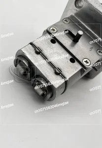
Original New Fuel Injection Pump Compatible For Kubota A721/751 16001-51011 104205-2051 9410617065 Excavator Engine Replacement Parts
YTTGHGHF Wide adaptation: compatible with various models and engines, convenient installation and strong versatility. || Precise pressure control: stabilize the oil supply pressure and ensure efficient atomization combustion of fuel. || Durable material: anti-corrosion, anti-wear, prolong service life and reduce failure risk. || Precision technology: high-precision manufacturing, ensuring close cooperation of parts and stable and reliable work. || Original New Fuel Injection Pump Compatible For Kubota A721/751 16001-51011 104205-2051 9410617065 Excavator Engine Replacement Parts
YTTGHGHF Wide adaptation: compatible with various models and engines, convenient installation and strong versatility. || Precise pressure control: stabilize the oil supply pressure and ensure efficient atomization combustion of fuel. || Durable material: anti-corrosion, anti-wear, prolong service life and reduce failure risk. || Precision technology: high-precision manufacturing, ensuring close cooperation of parts and stable and reliable work. || Original New Fuel Injection Pump Compatible For Kubota A721/751 16001-51011 104205-2051 9410617065 Excavator Engine Replacement Parts

Fuel Injection Pump 16001-51011 104205-2051 9410617065 Compatible For Kubota Z482
JUCAQYZT 【 Upgraded Material 】: Made of high-performance alloy, suitable for various extreme weather conditions, resistant to high temperatures and cold winters. A good fuel injection pump is crucial for engine power, fuel efficiency, and fuel economy. || 【 Non destructive installation 】: The installation is very simple, without complex installation processes, easy to get started, and does not damage your car. || 【 Improving Fuel Economy 】: High precision manufacturing processes ensure the accuracy of fuel metering and injection, and the internal fuel flow channels have been optimized to reduce pressure loss, atomize fuel, and improve fuel efficiency and economy. || 【 More Stable Operation 】: The excellent design minimizes noise and vibration during operation, providing you with a quieter and more comfortable driving experience. || Fuel Injection Pump 16001-51011 104205-2051 9410617065 Compatible For Kubota Z482
JUCAQYZT 【 Upgraded Material 】: Made of high-performance alloy, suitable for various extreme weather conditions, resistant to high temperatures and cold winters. A good fuel injection pump is crucial for engine power, fuel efficiency, and fuel economy. || 【 Non destructive installation 】: The installation is very simple, without complex installation processes, easy to get started, and does not damage your car. || 【 Improving Fuel Economy 】: High precision manufacturing processes ensure the accuracy of fuel metering and injection, and the internal fuel flow channels have been optimized to reduce pressure loss, atomize fuel, and improve fuel efficiency and economy. || 【 More Stable Operation 】: The excellent design minimizes noise and vibration during operation, providing you with a quieter and more comfortable driving experience. || Fuel Injection Pump 16001-51011 104205-2051 9410617065 Compatible For Kubota Z482
You can express buy:
USD 290.48
28-06-2025
28-06-2025
16001-51011 104205-2051 9410617065 Domestic New Fuel Injection Pump Compatible with Kubota Z482
Images:
USD 285.3

[29-Apr-2025]
USD 289.03

[17-Jun-2025]
Components :
| 0. | INJECTION-PUMP ASSEMBLY | 104205-2051 |
| 1. | _ | |
| 2. | FUEL INJECTION PUMP | |
| 3. | NUMBER PLATE | |
| 4. | _ | |
| 5. | CAPSULE | |
| 6. | ADJUSTING DEVICE | |
| 7. | NOZZLE AND HOLDER ASSY | |
| 8. | Nozzle and Holder | |
| 9. | Open Pre:MPa(Kqf/cm2) | |
| 10. | NOZZLE-HOLDER | |
| 11. | NOZZLE |
Scheme ###:
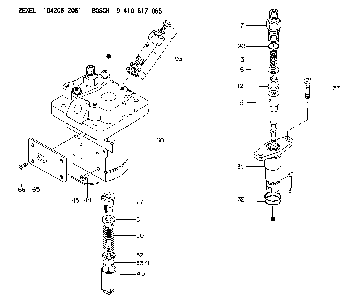
| 5. | [2] | 140154-1720 | PLUNGER-AND-BARREL ASSY |
| 12. | [2] | 140110-4420 | DELIVERY-VALVE ASSEMBLY |
| 13. | [2] | 140112-2800 | COMPRESSION SPRING |
| 16. | [2] | 140115-2200 | GASKET D12.8&8.6T0.5 |
| 17. | [2] | 140116-7820 | FITTING |
| 20. | [2] | 016550-1220 | O-RING |
| 30. | [2] | 140131-0021 | FLANGE BUSHING |
| 31. | [2] | 140271-0000 | BEARING PIN |
| 32. | [4] | 016550-1620 | O-RING |
| 37. | [4] | 140124-0100 | FLAT-HEAD SCREW |
| 40. | [2] | 140200-2320 | TAPPET |
| 44. | [2] | 140212-0300 | BEARING PIN |
| 45. | [1] | 140213-0800 | LOCKING WASHER |
| 50. | [2] | 140215-2000 | COMPRESSION SPRING |
| 51. | [2] | 140216-1300 | SLOTTED WASHER |
| 52. | [2] | 140254-2900 | SLOTTED WASHER |
| 53/1. | [1] | 140254-1400 | PLATE T1.80 |
| 53/1. | [1] | 140254-1500 | PLATE T1.85 |
| 53/1. | [1] | 140254-1600 | PLATE T1.90 |
| 53/1. | [1] | 140254-1700 | PLATE T1.95 |
| 53/1. | [1] | 140254-1800 | PLATE T2.00 |
| 53/1. | [1] | 140254-1900 | PLATE T2.05 |
| 53/1. | [1] | 140254-2000 | PLATE T2.10 |
| 53/1. | [1] | 140254-2100 | PLATE T2.15 |
| 53/1. | [1] | 140254-2200 | PLATE T2.20 |
| 53/1. | [1] | 140254-2300 | PLATE T2.25 |
| 53/1. | [1] | 140254-2400 | PLATE T2.30 |
| 53/1. | [1] | 140254-2500 | PLATE T2.35 |
| 53/1. | [1] | 140254-2600 | PLATE T2.40 |
| 53/1. | [1] | 140254-2700 | PLATE T2.45 |
| 53/1. | [1] | 140254-2800 | PLATE T2.50 |
| 53/1. | [1] | 140254-3100 | PLATE T1.825 |
| 53/1. | [1] | 140254-3200 | PLATE T1.875 |
| 53/1. | [1] | 140254-3300 | PLATE T1.925 |
| 53/1. | [1] | 140254-3400 | PLATE T1.975 |
| 53/1. | [1] | 140254-3500 | PLATE T2.025 |
| 53/1. | [1] | 140254-3600 | PLATE T2.075 |
| 53/1. | [1] | 140254-3700 | PLATE T2.125 |
| 53/1. | [1] | 140254-3800 | PLATE T2.175 |
| 53/1. | [1] | 140254-3900 | PLATE T2.225 |
| 53/1. | [1] | 140254-4000 | PLATE T2.275 |
| 53/1. | [1] | 140254-4100 | PLATE T2.325 |
| 53/1. | [1] | 140254-4200 | PLATE T2.375 |
| 53/1. | [1] | 140254-4300 | PLATE T2.425 |
| 53/1. | [1] | 140254-4400 | PLATE T2.475 |
| 53/1. | [1] | 140254-4500 | PLATE T2.525 |
| 60. | [1] | 140243-3620 | CONTROL ROD |
| 65. | [1] | 140262-0400 | PLATE |
| 66. | [4] | 140252-0000 | FLAT-HEAD SCREW |
| 77. | [2] | 140241-4021 | CONTROL SLEEVE |
| 93. | [1] | 140402-3020 | EYE BOLT |
Include in #1:
108062-3930
as _
Include in #2:
104205-2051
as INJECTION-PUMP ASSEMBLY
Cross reference number
Zexel num
Bosch num
Firm num
Name
104205-2051
1600151011 KUBOTA
FUEL-INJECTION PUMP
K 23MB FUEL INJECTION PUMP PFR-2MD PFR
K 23MB FUEL INJECTION PUMP PFR-2MD PFR
104205-2051
1600151011 KUBOTA
FUEL-INJECTION PUMP
K 23MB FUEL INJECTION PUMP PFR-2MD PFR
K 23MB FUEL INJECTION PUMP PFR-2MD PFR
Information:
1. Remove fuel line (1) from the fuel transfer pump.2. Put caps in the fuel line openings to prevent fuel system contamination.3. Remove bolts (2), and remove fuel transfer pump (3). Check the condition of the O-ring seal on the fuel transfer pump. If necessary, make a replacement. The following steps are for installation of the fuel transfer pump.4. Be sure the O-ring seal is in position on the fuel transfer pump. Put clean engine oil on the O-ring seal.5. Put fuel transfer pump (3) in position, and install the bolts that hold it in place.6. Remove the caps from the fuel line openings, and install fuel line (1).Disassemble Fuel Transfer Pump
Start By:a. remove fuel transfer pump 1. Remove seal (1) from the fuel transfer pump.
Cover (2) is under spring tension. Remove the bolts that hold cover (2) slowly to prevent injury.
2. Remove bolts (3) and cover (2) from the housing. 3. Remove seals (4) and valve (5) from cover (2). 4. Remove spring (6) from the piston.
Mark the orientation of valve (8) as to its location in the housing.
5. Remove washer (7), valve (8) and the seal from the housing. 6. Remove piston (9) and sleeve (10) from the housing. 7. Remove seal (11) from sleeve (12). 8. Remove guide and tappet assembly (13) from the housing. 9. Remove seal (14) from guide (15).
If tappet (17) or the guide are damaged or worn, they must be replaced as a unit.
10. Remove ring (16) from tappet (17) and the tappet from guide (15). 11. Remove the bolts and cover (18) from the housing. 12. Remove seal (19) from cover (18). 13. Remove valve (20) from the housing if necessary.Assemble Fuel Transfer Pump
1. Install valve (20) in housing as shown. 2. Put clean fuel on seal (19), and install it on cover (18).3. Install cover (18) on the housing.
The tappet and guide must be serviced as a unit.
4. Install tappet (17) in guide (15). Install ring (16) on tappet (17) to hold the tappet in the guide. 5. Put clean fuel on seal (14), and install it on guide and tappet assembly (13).6. Install guide and tappet assembly (13) in the housing as shown 7. Put clean fuel on seal (11), and install it on sleeve (12).8. Install sleeve (12) in the housing. 9. Install piston (9) in the housing. 10. Install seal, valve (8) and washer (7) in the housing as shown. Be sure valve (8) is the correct position in the housing. 11. Install spring (6) in the piston. 12. Install valve (5) in cover (2) as shown.13. Put clean fuel on seals (4), and put them in position on cover (2).14. Install cover (2) on the housing. 15. Put seal (1) in position on the fuel transfer pump.16. Install the fuel transfer pump on the fuel injection pump housing.End By:a. install fuel transfer pump