Information fuel-injection pump
BOSCH
9 410 617 488
9410617488
ZEXEL
104199-3040
1041993040
NIIGATA-TEKKOU
10447004A
10447004a
Rating:
Components :
| 0. | INJECTION-PUMP ASSEMBLY | 104199-3040 |
| 1. | _ | |
| 2. | FUEL INJECTION PUMP | |
| 3. | NUMBER PLATE | |
| 4. | _ | |
| 5. | CAPSULE | |
| 6. | ADJUSTING DEVICE | |
| 7. | NOZZLE AND HOLDER ASSY | |
| 8. | Nozzle and Holder | |
| 9. | Open Pre:MPa(Kqf/cm2) | |
| 10. | NOZZLE-HOLDER | |
| 11. | NOZZLE | 105012-5180 |
Scheme ###:
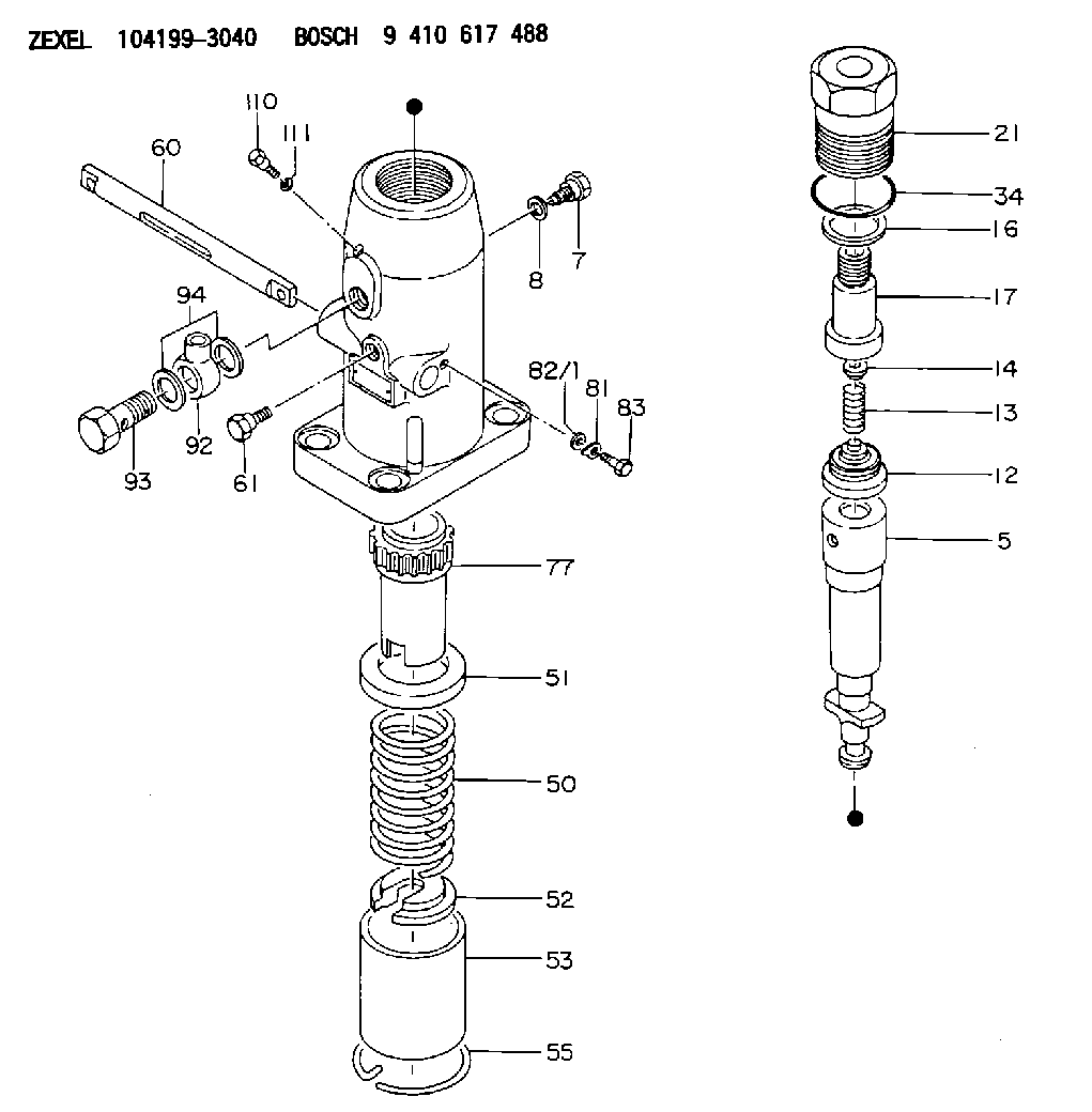
| 5. | [1] | 141172-0420 | PLUNGER-AND-BARREL ASSY |
| 7. | [1] | 141106-8600 | CAPSULE |
| 8. | [1] | 029331-2010 | GASKET |
| 12. | [1] | 141110-7520 | DELIVERY-VALVE ASSEMBLY |
| 13. | [1] | 141112-0201 | COMPRESSION SPRING |
| 14. | [1] | 141113-0300 | SLOTTED WASHER |
| 16. | [1] | 141115-4700 | GASKET |
| 17. | [1] | 141126-0900 | FITTING |
| 21. | [1] | 141119-0300 | NUT |
| 34. | [1] | 029636-5010 | O-RING |
| 50. | [1] | 141215-1400 | COMPRESSION SPRING |
| 51. | [1] | 141216-1200 | SLOTTED WASHER |
| 52. | [1] | 141217-3200 | SLOTTED WASHER |
| 53. | [1] | 141218-5520 | GUIDE |
| 55. | [1] | 141220-0700 | LOCKING WASHER |
| 60. | [1] | 141243-2000 | CONTROL RACK |
| 61. | [1] | 141226-3300 | BLEEDER SCREW |
| 77. | [1] | 141241-1700 | CONTROL SLEEVE |
| 81. | [1] | 141245-2000 | POINTER |
| 82/1. | [0] | 023500-6210 | PLAIN WASHER D11&6.4T1.5 |
| 82/1. | [0] | 029300-6010 | PLAIN WASHER D11&6.4T0.8 |
| 82/1. | [0] | 029300-6020 | PLAIN WASHER D11&6.4T0.35 |
| 83. | [1] | 020006-1440 | BLEEDER SCREW M6P1L14 |
| 92. | [1] | 029702-6020 | INLET UNION |
| 93. | [1] | 141402-6900 | EYE BOLT |
| 94. | [2] | 026526-3440 | GASKET |
| 110. | [1] | 140420-0600 | BLEEDER SCREW |
| 111. | [1] | 026506-1040 | GASKET D9.9&6.2T1 |
Include in #1:
107691-2410
as _
Include in #2:
104199-3040
as INJECTION-PUMP ASSEMBLY
Cross reference number
Zexel num
Bosch num
Firm num
Name
Information:
Illustration 15: (A) Injector sleeve. (3) Lower pilot. (36) Pipe or tubing.6. Place new injector sleeve (A) into its bore in the cylinder head. Wipe away any excess retaining compound that is either in or above the injector sleeve.7. Install lower pilot (3) into the injector sleeve. To avoid damage to the guide on the lower pilot (3), use a piece of pipe or tubing (36) with a small hammer to LIGHTLY tap the lower pilot. This will ensure that the new injector sleeve is fully seated in the cylinder head.Remove lower pilot (3).
Illustration 16: (14) Roller expander. (32) Mandrel.8. Place a coating of clean engine oil on 4C-6730 Roller Expander (14). Ensure the rollers are completely covered with oil.9. Pull and hold mandrel (32) out of the roller expander (14) as far as possible. Then completely insert the roller expander into the injector sleeve.10. Place a torque wrench with a 11 mm socket on the hex portion of 4C-6730 Roller Expander mandrel. Turn the torque wrench in a clockwise (CW) direction in order to achieve a torque of 11 N m (100 lb in). If torque stops increasing before 11 N m (100 lb in) the sleeve is not hard enough or the bore is oversized in the head.
To ensure that accurate torque is achieved, a calibrated 4C-6936 Torque Wrench or equivalent is required.
11. When the specified torque is reached, stop turning the roller expander in the clockwise (CW) direction. Now turn the roller expander in the counterclockwise (CCW) direction until it is loose in the injector sleeve.Remove 4C-6730 Roller Expander from the injector sleeve.12. Wipe the roller expander, especially the rollers, to remove any traces of 7M-7456 Bearing Mount or Loctite® 609 that may have built up from the injector sleeve. When usage of 4C-6730 Roller Expander is completed, clean it thoroughly using either 1U-8803 Cleaner Concentrate or 8T-9011 Component Cleaner. After the cleaning, place a generous coat of either 1U-8265 Penetrating Oil or 1U-8809 Rust Preventive on the roller expander. Place it in its storage case.
Illustration 17: (A) Injector sleeve. (13) Driver. (15) Guide bushing. Wage/flaring assembly: (8) Set screw. (9) Bottom swage. (11) Flare tool.13. Install 4C-6591 Bottom Swage (9) in 9U-6856 Flare Tool (11) using 4C-5502 Set Screw (8).14. Slide same guide bushing (15) used previously onto 9U-6856 Flare Tool (11).
Some 9U-6856 Flare Tools have their part number stamped on the turn which fits into the guide bushing. This arrangement interferes with the fit. Before the first tool use, the part number should be filed down as necessary in order to permit fit of the flare tool in the guide bushing.
15. Use 5P-3931 Anti-seize Compound, 6V-4876 Molykote Paste Lubricant, or grease to lubricate the swage/flaring assembly. Place it into the sleeve with the flare tool prying notch facing either opening between the valve springs. This will allow access for removal of the swage/flaring assembly.16. Place 9U-6857 Driver (13) on 9U-6856 Flare Tool (11).17. Use a hammer to drive down the swage/flaring assembly until