Information fuel-injection pump
BOSCH
9 410 617 487
9410617487
ZEXEL
104199-3000
1041993000
NIIGATA-URAWA
10447000C
10447000c
Rating:
Components :
| 0. | INJECTION-PUMP ASSEMBLY | 104199-3000 |
| 1. | _ | |
| 2. | FUEL INJECTION PUMP | |
| 3. | NUMBER PLATE | |
| 4. | _ | |
| 5. | CAPSULE | |
| 6. | ADJUSTING DEVICE | |
| 7. | NOZZLE AND HOLDER ASSY | |
| 8. | Nozzle and Holder | |
| 9. | Open Pre:MPa(Kqf/cm2) | |
| 10. | NOZZLE-HOLDER | |
| 11. | NOZZLE |
Scheme ###:
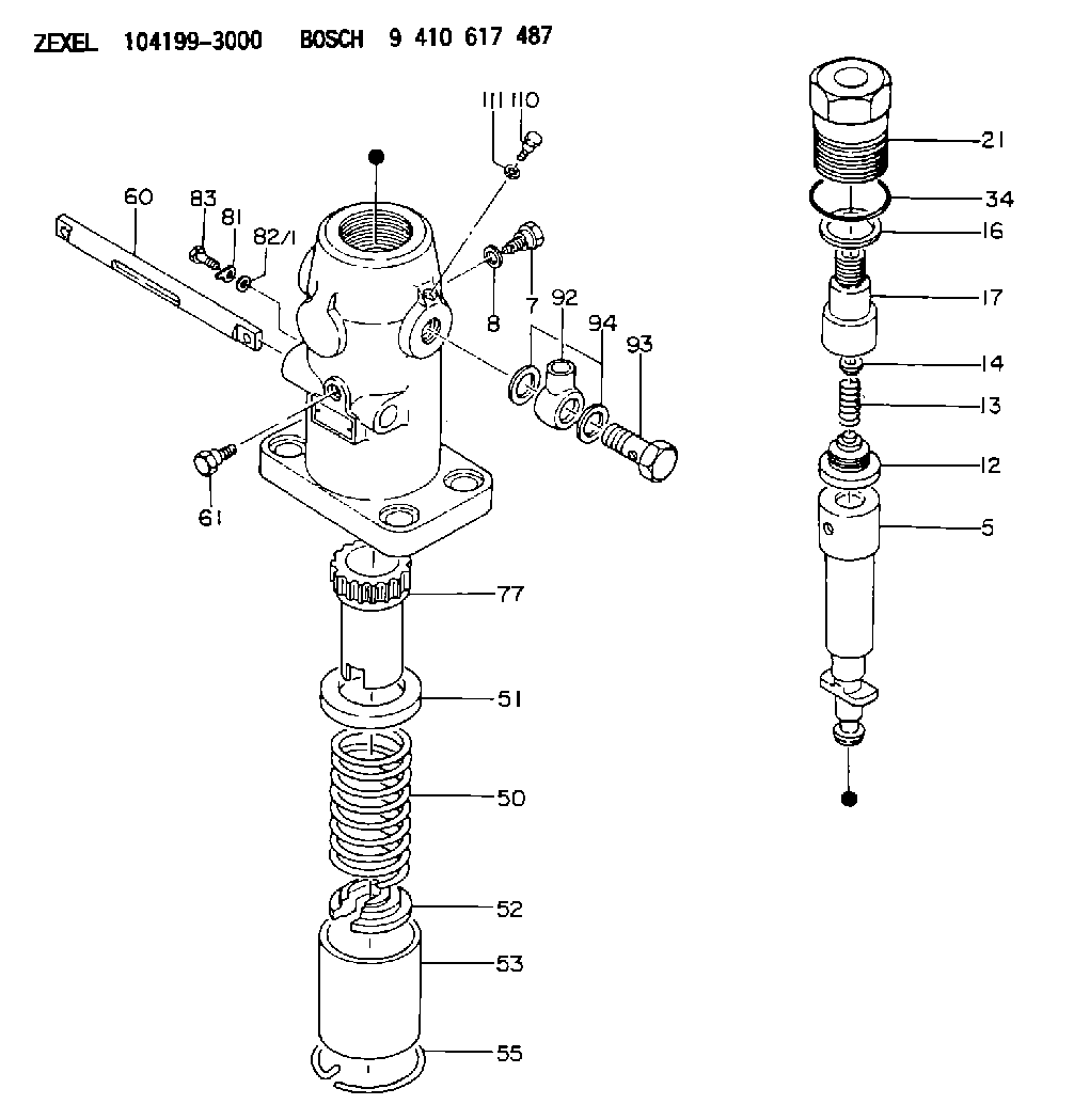
| 5. | [1] | 141172-0420 | PLUNGER-AND-BARREL ASSY |
| 7. | [1] | 141106-8600 | CAPSULE |
| 8. | [1] | 029331-2010 | GASKET |
| 12. | [1] | 141110-3920 | DELIVERY-VALVE ASSEMBLY |
| 13. | [1] | 141112-0201 | COMPRESSION SPRING |
| 14. | [1] | 141113-0300 | SLOTTED WASHER |
| 16. | [1] | 141115-4700 | GASKET |
| 17. | [1] | 141126-0900 | FITTING |
| 21. | [1] | 141119-0300 | NUT |
| 34. | [1] | 029636-5010 | O-RING |
| 50. | [1] | 141215-1400 | COMPRESSION SPRING |
| 51. | [1] | 141216-1200 | SLOTTED WASHER |
| 52. | [1] | 141217-3200 | SLOTTED WASHER |
| 53. | [1] | 141218-5520 | GUIDE |
| 55. | [1] | 141220-0700 | LOCKING WASHER |
| 60. | [1] | 141243-2000 | CONTROL RACK |
| 61. | [1] | 141226-3300 | BLEEDER SCREW |
| 77. | [1] | 141241-1700 | CONTROL SLEEVE |
| 81. | [1] | 141245-2000 | POINTER |
| 82/1. | [0] | 023500-6210 | PLAIN WASHER D11&6.4T1.5 |
| 82/1. | [0] | 029300-6010 | PLAIN WASHER D11&6.4T0.8 |
| 82/1. | [0] | 029300-6020 | PLAIN WASHER D11&6.4T0.35 |
| 83. | [1] | 020006-1440 | BLEEDER SCREW M6P1L14 |
| 92. | [1] | 029702-6020 | INLET UNION |
| 93. | [1] | 029732-6010 | EYE BOLT |
| 94. | [2] | 026526-3440 | GASKET |
| 110. | [1] | 141420-1600 | BLEEDER SCREW |
| 111. | [1] | 026506-1040 | GASKET D9.9&6.2T1 |
Include in #1:
101608-6334
as _
Include in #2:
104199-3000
as INJECTION-PUMP ASSEMBLY
Cross reference number
Zexel num
Bosch num
Firm num
Name
104199-3000
10447000C NIIGATA-URAWA
FUEL-INJECTION PUMP
K 24JA FUEL INJECTION PUMP PF-1DD(V) PF
K 24JA FUEL INJECTION PUMP PF-1DD(V) PF
104199-3000
10447000B
FUEL-INJECTION PUMP
K 24JA FUEL INJECTION PUMP PF-1DD(V) PF
K 24JA FUEL INJECTION PUMP PF-1DD(V) PF
Information:
B. Back out (loosen) the lift adjustment screw 3/4 1/8of a turn.C. Put the nozzle in a vise with 8S2250 Holding Tool (1). Hold pressure adjusting screw (4) and tighten the locknut to a torque of 8.0-8.5 N m (70-75 lb in) using the 2P5487 Adapter (A). Recheck the opening pressure.Adjustment of 9L7883 Nozzles
1. Remove the nozzle from the tester and place in a vise using 8S2250 Nozzle Holding Tool (1). Loosen lift adjusting screw locknut (2). Loosen lift adjusting screw (3) two full turns counterclockwise.
If lift adjusting screw (3) is not loosened, the valve can be damaged in later steps.
2. Loosen pressure adjusting screw (4) and remove the nozzle from the nozzle holding tool. 3. Tilt the nozzle slightly down from the vertical position and remove pressure screw (4) and shims (5). If the shims do not come out of the nozzle, invert the nozzle and let the shims, spring and spring seat fall into the hand. If the valve comes out of its own weight, handle it carefully by its stem.4. To increase the opening pressure, add a 4N5730 Shim. The 4N5730 Shim is 0.13 mm (.005") thick and will increase the opening pressure approximately 1725 kPa (250 psi). A maximum of two shims can be added; if two shims do not increase opening pressure to specification given, discard the nozzle. 5. Assemble the nozzle, making sure the thickest shim (C) is against pressure screw (4). Put the nozzle in a vise using 8S2250 Nozzle Holding Tool (1). Tighten the pressure adjusting screw to 8.0-9.1 N m (70-80 lb in) torque.6. Remove the nozzle from the holding tool. Connect the nozzle, with the tip facing downward, to the tester. Point the nozzle tip into the 8S2270 Fuel Collector and the FT1384 Extension. Check the opening pressure and if it is not within specifications, repeat steps 4 and 5.Valve Lift Adjustment-9L7883 Nozzles
A. When the correct opening pressure is set, and while pumping test fluid through the nozzle, hold the lift adjusting screw locknut and slowly turn the lift adjusting screw clockwise (CW) until valve pressure rises 1380-3450 kPa (200-500 psi) above the nozzle opening pressure. Some test fluid may collect on the tip, but it must not flow at a rapid dribble.
Do not bend the valve by bottoming with too much force.
B. Back out the lift screw 3/4 1/8 turn, hold the lift adjusting screw, and tighten the locknut just enough so the screw will not turn; the lift is now set. C. Put the nozzle in a vise using 8S2250 Holding Tool (1). Tighten the locknut to 4.0-4.5 N m (35-40 lb in). Recheck valve opening pressure.Adjustment of 9L6969, 7N0449, 9N3299, 9N3700, 9N3979, 1W5829, 4W1819, 4W8483 and 7W3710 Nozzles
1. Put the nozzle in a vise using the 8S2250 Holding Tool (1). Loosen lift adjusting screw locknut (2). Turn lift adjusting screw (3) two full turns counterclockwise (CCW). 2. Hold lift adjusting screw (3) with a .08 mm (5/64") hex wrench (4) and