Information fuel-injection pump
ZEXEL
104198-0311
1041980311

Rating:
Components :
| 0. | INJECTION-PUMP ASSEMBLY | 104198-0311 |
| 1. | _ | |
| 2. | FUEL INJECTION PUMP | |
| 3. | NUMBER PLATE | |
| 4. | _ | |
| 5. | CAPSULE | |
| 6. | ADJUSTING DEVICE | |
| 7. | NOZZLE AND HOLDER ASSY | |
| 8. | Nozzle and Holder | |
| 9. | Open Pre:MPa(Kqf/cm2) | |
| 10. | NOZZLE-HOLDER | |
| 11. | NOZZLE |
Scheme ###:
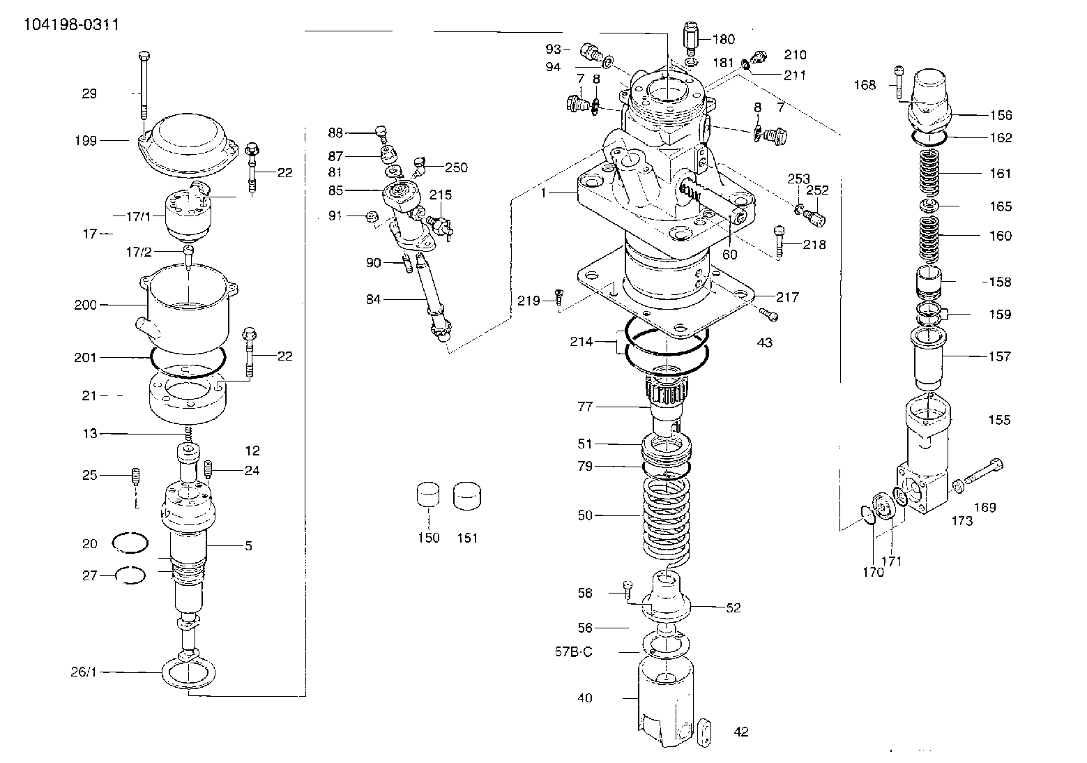
| 1. | [1] | 141055-7120 | PUMP HOUSING |
| 5. | [1] | 141157-0520 | PLUNGER-AND-BARREL ASSY PC149 |
| 7. | [2] | 141133-3800 | CAPSULE |
| 8. | [2] | 141107-0300 | GASKET |
| 12. | [1] | 141140-9820 | DELIVERY-VALVE ASSEMBLY PC15 |
| 13. | [1] | 141112-6600 | COMPRESSION SPRING |
| 17. | [1] | 141137-0920 | FITTING |
| 17/1. | [1] | 141137-0900 | FITTING |
| 17/2. | [1] | 141117-5300 | FILLER PIECE |
| 20. | [2] | 141482-2800 | O-RING |
| 21. | [1] | 141119-3900 | FLANGE BUSHING |
| 22. | [12] | 141124-2300 | BLEEDER SCREW |
| 24. | [1] | 011012-2520 | SET OF NUTS |
| 25. | [1] | 011112-3020 | SET OF NUTS |
| 26/1. | [1] | 141161-0800 | SPACER BUSHING T4 |
| 26/1. | [1] | 141161-0900 | SPACER BUSHING T4.5 |
| 26/1. | [1] | 141161-1000 | SPACER BUSHING T5 |
| 26/1. | [1] | 141161-1100 | SPACER BUSHING T5.5 |
| 26/1. | [1] | 141161-1200 | SPACER BUSHING T6 |
| 26/1. | [1] | 141161-1300 | SPACER BUSHING T6.5 |
| 26/1. | [1] | 141161-1400 | SPACER BUSHING T7 |
| 26/1. | [1] | 141161-1500 | SPACER BUSHING T7.5 |
| 26/1. | [1] | 141161-1600 | SPACER BUSHING T8 |
| 26/1. | [1] | 141161-2800 | SPACER BUSHING T3.5 |
| 26/1. | [1] | 141161-2900 | SPACER BUSHING T8.5 |
| 27. | [2] | 141482-2900 | O-RING |
| 29. | [2] | 141124-2600 | BLEEDER SCREW |
| 40. | [1] | 141200-1120 | TAPPET |
| 42. | [1] | 141213-0500 | PLATE |
| 43. | [2] | 010212-3520 | HEX-SOCKET-HEAD CAP SCREW |
| 50. | [1] | 141215-3700 | COMPRESSION SPRING |
| 51. | [1] | 141216-3220 | SLOTTED WASHER |
| 52. | [1] | 141217-5800 | SLOTTED WASHER |
| 56. | [1] | 141254-0100 | SPACER BUSHING |
| 57. | [1] | 141209-0100 | SHIM |
| 57B. | [1] | 141209-0200 | SHIM |
| 57C. | [1] | 141209-0700 | SHIM |
| 58. | [2] | 010208-2020 | HEX-SOCKET-HEAD CAP SCREW |
| 60. | [1] | 141244-3900 | CONTROL RACK |
| 77. | [1] | 141241-7520 | CONTROL SLEEVE |
| 79. | [1] | 141482-0500 | O-RING |
| 81. | [1] | 141245-3600 | POINTER |
| 84. | [1] | 141240-0600 | PINION |
| 85. | [1] | 141440-1220 | FLANGE BUSHING |
| 87. | [1] | 141439-1400 | BUSHING |
| 88. | [1] | 141418-0100 | BLEEDER SCREW |
| 90. | [2] | 141438-1700 | STUD |
| 91. | [2] | 141439-1900 | UNION NUT |
| 93. | [2] | 141416-0500 | CONNECTOR |
| 94. | [2] | 141403-0300 | GASKET |
| 150. | [2] | 375160-2300 | CAPSULE |
| 151. | [1] | 029926-0000 | CAP |
| 155. | [1] | 141454-1200 | HOUSING;ACCUMULATOR |
| 156. | [1] | 141455-0701 | COVER;ACCUMULATOR |
| 157. | [1] | 141456-0900 | CYLINDER |
| 158. | [1] | 141276-0900 | PUMP PLUNGER |
| 159. | [2] | 141457-0000 | PISTON RING |
| 160. | [1] | 141258-1800 | COILED SPRING |
| 161. | [1] | 141258-1900 | COILED SPRING |
| 162. | [1] | 141482-0400 | O-RING |
| 165. | [1] | 141217-7200 | SLOTTED WASHER |
| 168. | [2] | 141269-0100 | HEX-SOCKET-HEAD CAP SCREW |
| 169. | [4] | 141263-1400 | BLEEDER SCREW |
| 170. | [2] | 141485-5600 | O-RING |
| 171. | [1] | 141450-2000 | ORIFICE |
| 180. | [1] | 141124-2700 | CONNECTOR |
| 181. | [1] | 141406-0900 | GASKET |
| 199. | [1] | 141130-1200 | COVER |
| 200. | [1] | 141130-1300 | COVER |
| 201. | [1] | 141482-0600 | O-RING |
| 210. | [1] | 141405-0600 | CAPSULE |
| 211. | [1] | 141406-0300 | GASKET |
| 214. | [2] | 141482-0700 | O-RING |
| 215. | [1] | 141239-0620 | FILLER PIECE |
| 217. | [1] | 141209-5700 | PLATE |
| 218. | [2] | 141418-4200 | BLEEDER SCREW |
| 219. | [4] | 010708-2520 | FLAT-HEAD SCREW |
| 250. | [1] | 141270-0300 | HINGED LID |
| 252. | [1] | 141416-1800 | CONNECTOR |
| 253. | [1] | 141406-0300 | GASKET |
Include in #1:
101608-1803
as _
Include in #2:
104198-0311
as INJECTION-PUMP ASSEMBLY
Cross reference number
Zexel num
Bosch num
Firm num
Name
104198-0311
FUEL-INJECTION PUMP
24LF FUEL INJECTION PUMP PF-PC4-2 PF
24LF FUEL INJECTION PUMP PF-PC4-2 PF
Information:
(3) Remove all dirt, rust and foreign material from the surfaces on transmission input flange (3), shaft assembly (4) and spacer group (2). Use a file to remove all burrs or damaged areas on the surfaces. Install shaft assembly (4) on flange (3) with bolts (5) and the nuts. Push the crankshaft to the front of its travel with a pry bar. Loosely install spacer (2). Put a feeler gauge equal to one-half the crankshaft end play (see step 2, page 6 for the dimension) between spacer (2) and coupling (1) at (S). Move the engine to the front or rear as needed to get clearance equal to the feeler gauge thickness. Remove spacer (2). Install 6V2042 Alignment Yoke (6) and 6V2043 Alignment Bar (7) on shaft (4) with two 13.0 mm Ø (.5"Ø) threaded rods and nuts. Install two dial indicators (8) and (9) as shown, one on surface (Y) and one on surface (Z). Use a pry bar to push the crankshaft to the front of its travel. Set the indicators to "0" in this position. (4) Indicator (8), on surface (Y), will show face alignment. Slowly turn shaft (4) by hand; do not use yoke (6) to turn the shaft. Make a record of the indicator readings 90° apart at (A), (B), (C) and (D). Face alignment as shown by the indicator must be as follows: a) A maximum TIR between (A) and (C) of 0.25 mm (.010") is permitted. The reading at (C) must be plus (+). This dimension is needed, because as an application of engine torque is made to the propeller shaft, the transmission will tip forward a small amount and both dimensions will be the same.b) A maximum TIR between (B) and (D) of 0.25 mm (0.010") is permitted but the reading at (B) plus the reading at (D) must be equal to the reading at (C). (5) Indicator (9) on surface (Z) will show bore alignment. Put the indicator on "0" at location (A). Slowly turn shaft (4) and make a record of the indicator readings 90° apart at (A), (B), (C) and (D). Bore alignment as shown by indicator (9) must be as follows: a) The TIR between (A) and (C) must be 0.64 0.25 mm (.025" .010"). IMPORTANT: Because the centerline of the crankshaft must be below the centerline of the coupling shaft, the indicator reading at (C) must be plus (+) when the reading at (A) is 0.00 mm (.000") and indicator (9) is installed as shown.b) The TIR between (B) and (D) can be a maximum of 0.13 (.005"). The reading at (B) plus (D) must equal the reading at (C).(6) Move the engine as necessary to get the alignment dimensions given. (7) Loosely connect shaft (4) to coupling (1) with two bolts (18). Do not install the spacer between the shaft and the coupling at this time. Rotate the engine and transmission input shaft together and take the dial indicator readings
Have questions with 104198-0311?
Group cross 104198-0311 ZEXEL
104198-0311
FUEL-INJECTION PUMP