Information fuel-injection pump
BOSCH
9 410 617 163
9410617163
ZEXEL
104198-0191
1041980191
ISHIKAWAJIMA-H
121040016
121040016
Rating:
Components :
| 0. | INJECTION-PUMP ASSEMBLY | 104198-0191 |
| 1. | _ | |
| 2. | FUEL INJECTION PUMP | |
| 3. | NUMBER PLATE | |
| 4. | _ | |
| 5. | CAPSULE | |
| 6. | ADJUSTING DEVICE | |
| 7. | NOZZLE AND HOLDER ASSY | |
| 8. | Nozzle and Holder | |
| 9. | Open Pre:MPa(Kqf/cm2) | |
| 10. | NOZZLE-HOLDER | |
| 11. | NOZZLE |
Scheme ###:
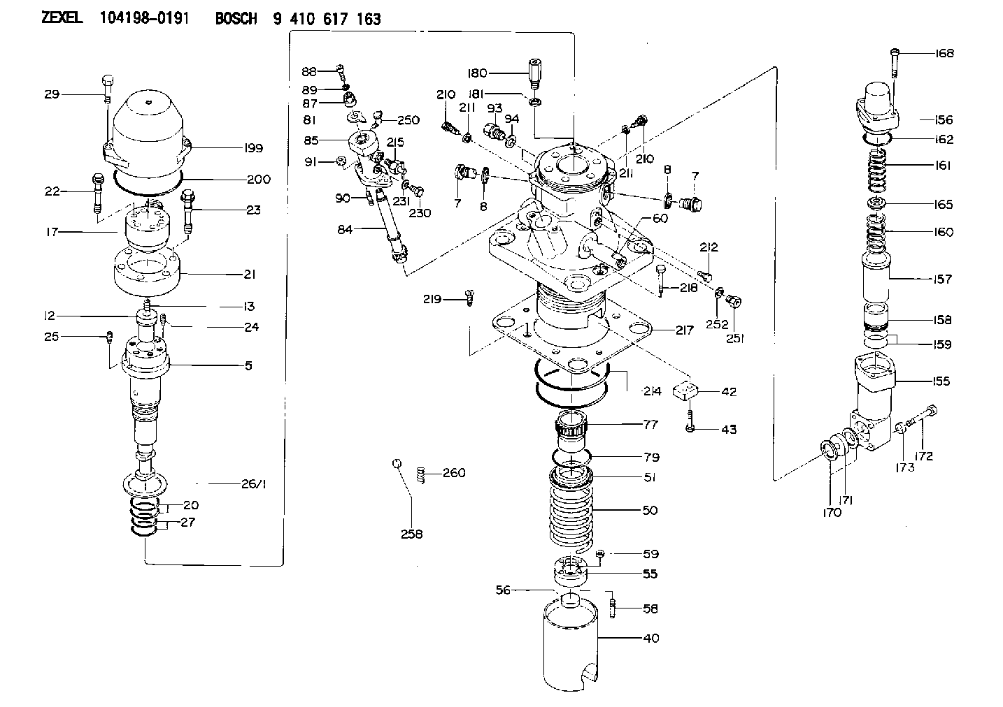
| 5. | [1] | 141156-5422 | PLUNGER-AND-BARREL ASSY |
| 7. | [2] | 141133-3800 | CAPSULE |
| 7. | [2] | 141133-3800 | CAPSULE |
| 8. | [2] | 141107-0300 | GASKET |
| 8. | [2] | 141107-0300 | GASKET |
| 12. | [1] | 141142-3920 | DELIVERY-VALVE ASSEMBLY |
| 13. | [1] | 141112-6600 | COMPRESSION SPRING |
| 17. | [1] | 141137-3420 | FITTING |
| 20. | [2] | 141482-2800 | O-RING |
| 21. | [1] | 141119-4500 | FLANGE BUSHING |
| 22. | [6] | 141124-3900 | BLEEDER SCREW |
| 23. | [6] | 141124-4000 | BLEEDER SCREW |
| 24. | [1] | 011008-2520 | SET OF NUTS |
| 25. | [1] | 011108-3020 | SET OF NUTS |
| 26/1. | [1] | 141161-0800 | SPACER BUSHING T4 |
| 26/1. | [1] | 141161-0900 | SPACER BUSHING T4.5 |
| 26/1. | [1] | 141161-1000 | SPACER BUSHING T5 |
| 26/1. | [1] | 141161-1100 | SPACER BUSHING T5.5 |
| 26/1. | [1] | 141161-1200 | SPACER BUSHING T6 |
| 26/1. | [1] | 141161-1300 | SPACER BUSHING T6.5 |
| 26/1. | [1] | 141161-1400 | SPACER BUSHING T7 |
| 26/1. | [1] | 141161-1500 | SPACER BUSHING T7.5 |
| 26/1. | [1] | 141161-1600 | SPACER BUSHING T8 |
| 26/1. | [1] | 141161-2800 | SPACER BUSHING T3.5 |
| 26/1. | [1] | 141161-2900 | SPACER BUSHING T8.5 |
| 27. | [2] | 141482-2900 | O-RING |
| 29. | [2] | 141124-5101 | BLEEDER SCREW |
| 40. | [1] | 141200-1720 | TAPPET |
| 42. | [1] | 141213-1200 | PLATE |
| 43. | [2] | 141263-1000 | BLEEDER SCREW |
| 50. | [1] | 141215-7300 | COMPRESSION SPRING |
| 51. | [1] | 141216-4920 | SLOTTED WASHER |
| 55. | [1] | 141221-0200 | SPACER BUSHING |
| 56. | [1] | 141254-0600 | SPACER BUSHING |
| 58. | [4] | 141438-2100 | STUD |
| 59. | [4] | 141439-2300 | UNION NUT |
| 60. | [1] | 141244-3900 | CONTROL RACK |
| 77. | [1] | 141292-0320 | CONTROL SLEEVE |
| 79. | [1] | 141482-8300 | O-RING |
| 81. | [1] | 141245-3920 | POINTER |
| 84. | [1] | 141240-0400 | PINION |
| 85. | [1] | 141440-1020 | FLANGE BUSHING |
| 87. | [1] | 141439-2200 | UNION NUT |
| 88. | [1] | 010212-4020 | HEX-SOCKET-HEAD CAP SCREW |
| 89. | [1] | 014011-2110 | PLAIN WASHER |
| 90. | [2] | 141438-1700 | STUD |
| 91. | [2] | 141439-1900 | UNION NUT |
| 93. | [2] | 141416-0500 | CONNECTOR |
| 94. | [2] | 141403-0300 | GASKET |
| 155. | [1] | 141454-0700 | HOUSING;ACCUMULATOR |
| 156. | [1] | 141455-0900 | COVER;ACCUMULATOR |
| 157. | [1] | 141456-0200 | CYLINDER |
| 158. | [1] | 141276-0900 | PUMP PLUNGER |
| 159. | [2] | 141457-0000 | PISTON RING |
| 160. | [1] | 141258-1800 | COILED SPRING |
| 161. | [1] | 141258-1900 | COILED SPRING |
| 162. | [1] | 141482-0400 | O-RING |
| 165. | [1] | 141217-7200 | SLOTTED WASHER |
| 168. | [4] | 141269-0800 | HEX-SOCKET-HEAD CAP SCREW |
| 170. | [2] | 141406-1400 | GASKET |
| 171. | [1] | 141450-0800 | ORIFICE |
| 172. | [4] | 141263-1100 | BLEEDER SCREW |
| 173. | [4] | 141248-0800 | SPACER BUSHING |
| 180. | [1] | 141416-1500 | CONNECTOR |
| 181. | [1] | 141406-0900 | GASKET D35&27.4T1.0 |
| 199. | [1] | 141130-1700 | COVER |
| 200. | [1] | 141482-0700 | O-RING |
| 210. | [2] | 141405-3600 | CAPSULE |
| 210. | [2] | 141405-3600 | CAPSULE |
| 211. | [2] | 141406-1300 | GASKET |
| 211. | [2] | 141406-1300 | GASKET |
| 212. | [1] | 141263-0600 | BLEEDER SCREW |
| 214. | [2] | 141482-0700 | O-RING |
| 215. | [1] | 141239-0520 | FILLER PIECE |
| 217. | [1] | 141209-2000 | PLATE |
| 218. | [2] | 141418-0400 | BLEEDER SCREW |
| 219. | [4] | 141483-0100 | FLAT-HEAD SCREW |
| 230. | [1] | 141266-0400 | FLAT-HEAD SCREW |
| 231. | [1] | 029341-2040 | GASKET |
| 250. | [1] | 141270-0300 | HINGED LID |
| 251. | [1] | 141405-3500 | CONNECTOR |
| 252. | [1] | 141406-1300 | GASKET |
| 258. | [1] | 029926-0000 | CAP |
| 260. | [1] | 141258-0500 | COILED SPRING |
Include in #1:
101401-1950
as _
Include in #2:
104198-0191
as INJECTION-PUMP ASSEMBLY
Cross reference number
Zexel num
Bosch num
Firm num
Name
104198-0191
9 410 617 163
121040016 ISHIKAWAJIMA-H
FUEL-INJECTION PUMP
K
K
Information:
Torque for Standard Bolts, Nuts and Taperlock Studs
The following charts give general torques for bolts, nuts, and taperlock studs. For torque specifications not included in this section, refer to Torque Specifications, SENR3130, available from your Caterpillar dealer.
Torques for Bolts and Nuts With Standard Threads
Torques for Taperlock Studs
Use these standard torque values for all fasteners, unless otherwise specified in this manual or in the Service Manual.Torque for Metric Fasteners
Be very careful never to mix metric with customary (SAE standard) fasteners. Mismatched or incorrect fasteners will cause engine damage or malfunction and may even result in personal injury.Original fasteners removed from the engine should be saved for reassembly whenever possible. If new fasteners are needed, they must be of the same size and grade as the ones that are being replaced.
Material strength identification is usually shown on the bolt head by numbers (8.8, 10.9, etc.). The following chart gives general torque values for bolts and nuts. Use these standard torque values unless otherwise specified in this publication. Metric hardware must be replaced with metric hardware. Check Parts Manual for proper replacement.Torques for Bolts and Nuts with Metric Threads
Torque for Standard Hose Clamps-Worm Drive Band Type
The following chart gives the torques for initial installation of hose clamps on new hose and for reassembly or tightening of hose clamps on existing hose. Torque for Constant Torque Hose Clamps
Due to extreme temperature changes, hose will heat set. Heat settings causes hose clamps to loosen. Loose hose clamps can result in leaks. There have been reports of component failures caused by hose clamps loosening. The new constant torque hose clamp will help prevent these failures. A constant torque hose clamp can be used in place of any standard hose clamp. Make sure the constant torque hose clamp is the same size as the standard clamp.
Installation
Each installation application can be different depending on the type of hose, fitting material, and anticipated expansion or contraction of the hose and fittings. A torque wrench should be used for proper installation of constant torque hose clamps. Constant torque hose clamps should be installed as follows:* To allow for maximum expansion, install clamps at 5.7 N m (50 lb in).* To allow for equal expansion and contraction, install clamps at 10.2 N m (90 lb in).* To allow for maximum contraction, install clamps at 14.1 N m (125 lb in).
Have questions with 104198-0191?
Group cross 104198-0191 ZEXEL
Niigata-Urawa
Niigata-Tekkou
Niigata-Urawa
Niigata-Urawa
Niigata-Tekkou
Nkk
Ishikawajima-H
104198-0191
9 410 617 163
121040016
FUEL-INJECTION PUMP