Information fuel-injection pump
BOSCH
9 410 617 112
9410617112
ZEXEL
104196-0302
1041960302
Rating:
Components :
| 0. | INJECTION-PUMP ASSEMBLY | 104196-0302 |
| 1. | _ | |
| 2. | FUEL INJECTION PUMP | |
| 3. | NUMBER PLATE | |
| 4. | _ | |
| 5. | CAPSULE | |
| 6. | ADJUSTING DEVICE | |
| 7. | NOZZLE AND HOLDER ASSY | |
| 8. | Nozzle and Holder | |
| 9. | Open Pre:MPa(Kqf/cm2) | |
| 10. | NOZZLE-HOLDER | |
| 11. | NOZZLE |
Scheme ###:
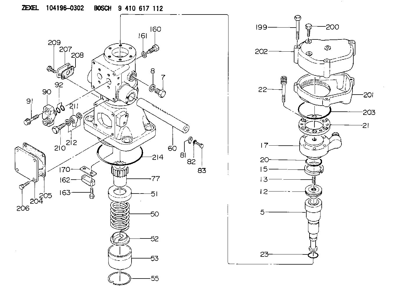
| 5. | [1] | 141156-8220 | PLUNGER-AND-BARREL ASSY |
| 7. | [2] | 141133-0701 | CAPSULE |
| 8. | [2] | 026524-2940 | GASKET D28.9&24.3T2 |
| 12. | [1] | 141140-8320 | DELIVERY-VALVE ASSEMBLY |
| 13. | [1] | 141112-3800 | COMPRESSION SPRING |
| 15. | [1] | 141220-2100 | LOCKING WASHER |
| 17. | [1] | 141136-5020 | FITTING |
| 20. | [1] | 141482-3200 | O-RING |
| 21. | [1] | 141119-4000 | FLANGE BUSHING |
| 22. | [6] | 141124-1800 | BLEEDER SCREW |
| 23. | [1] | 141482-3100 | O-RING |
| 50. | [1] | 141215-9100 | COMPRESSION SPRING |
| 51. | [1] | 141216-3700 | SLOTTED WASHER |
| 52. | [1] | 141217-5900 | SLOTTED WASHER |
| 53. | [1] | 141218-8121 | GUIDE |
| 55. | [1] | 141220-1800 | LOCKING WASHER |
| 60. | [1] | 141244-6800 | CONTROL RACK |
| 77. | [1] | 141241-7600 | CONTROL SLEEVE |
| 81. | [8] | 141245-4300 | POINTER |
| 82. | [2] | 014020-6120 | PLAIN WASHER |
| 83. | [2] | 010006-1400 | BLEEDER SCREW M6P1L14 7T |
| 90. | [2] | 141401-3300 | FLANGE BUSHING |
| 91. | [4] | 141124-1901 | BLEEDER SCREW |
| 92. | [4] | 016500-2850 | O-RING |
| 160. | [1] | 141124-2000 | BLEEDER SCREW |
| 161. | [1] | 026512-1840 | GASKET D17.9&12.2T1.50 |
| 162. | [1] | 141209-1101 | SHIM |
| 163. | [2] | 010010-2500 | BLEEDER SCREW |
| 170. | [1] | 141209-4700 | SHIM |
| 199. | [3] | 010010-9000 | BLEEDER SCREW |
| 200. | [3] | 141124-2100 | BLEEDER SCREW |
| 201. | [1] | 141130-0800 | COVER |
| 202. | [1] | 141130-0900 | COVER |
| 203. | [1] | 141482-3000 | O-RING |
| 204. | [1] | 141010-4600 | COVER |
| 205. | [1] | 141011-0600 | GASKET |
| 206. | [4] | 010042-2000 | BLEEDER SCREW |
| 207. | [1] | 141010-2400 | COVER |
| 208. | [1] | 141011-0500 | GASKET |
| 209. | [2] | 010010-2500 | BLEEDER SCREW |
| 210. | [1] | 027414-2620 | EYE BOLT |
| 211. | [1] | 027114-1020 | INLET UNION |
| 212. | [2] | 026514-1840 | GASKET D17.9&14.2T1 |
| 214. | [1] | 141482-3300 | O-RING |
Include in #1:
106861-2631
as _
Include in #2:
104196-0302
as INJECTION-PUMP ASSEMBLY
Cross reference number
Zexel num
Bosch num
Firm num
Name
Information:
17. Add coolant mixture if necessary to bring the coolant to within 13 mm (1/2 inch) below the bottom of the fill tube or the correct level on the sight glass, if equipped. Upon initial fill the sight gauge can indicate an incorrect coolant level. Be sure the coolant is to the bottom of the fill tube. Recheck the coolant level and fill the cooling system to the bottom of the fill tube if the system was low.
In cold weather, frequently check the specific gravity of the coolant solution to ensure adequate protection.If the engine is to be stored in, or shipped to an area with freezing temperatures, the cooling system must be either protected to the lowest expected outside temperature or drained completely to prevent damage. Always check your cooling system before operating your engine. Depending on load, failure to operate with thermostats could result in either an overheating or an excessive cooling condition.
18. Check the condition of the filler cap gasket (if equipped). If the gasket is damaged, discard the old filler cap and install a new filler cap. 19. Stop the engine and check the coolant to ensure it is at the proper level. Every 10,000 Hour Cleaning Procedure-Oil Cooler and Aftercooler Core
Caterpillar recommends that the oil cooler and aftercooler cores be removed, cleaned and pressure tested at Every 10,000 Hour overhaul time, or if a turbocharger failure has occurred, or if at any time the turbocharger develops an oil leak.1. Remove the core. Turn the core upside down to remove debris from the inlet.
Do not use caustic cleaners to clean the core. Caustic cleaners will attack the internal metals of the core and cause leakage.
2. Back flush internally with a solvent to loosen foreign substances and to remove oil. Caterpillar recommends the use of Caterpillar Hydrosolv 4165 or Hydrosolv 100 Liquid Cleaners. 3. Shake the core vigorously to eliminate any trapped debris. 4. Wash the core with hot, soapy water. Rinse thoroughly with clean water. 5. Dry the core with compressed air. Blow air in reverse direction of normal flow. Use all necessary safety equipment while using compressed air. 6. Inspect the system to ensure cleanliness and install the core. SR4 Generator
Make sure residual voltage in the rotor, stator and the generator is discharged.If this generator is to be connected to a utility electrical distribution system, it must be isolated from the distribution system by means of:a. Opening the main switch in the case of the generator temporarily connected to the system or,b. A double throw (transfer) switch in the case of a permanent connection to the system.Failure to do so could result in personal injury or death due to electrical shock. This warning does not apply when a generator and utility distribution system are designed and approved by the utility to run in parallel.
Before working inside the generator, make sure that the starting motor can not be activated by any automatic or manual signal.Electronic components in the regulator can be damaged during generator