Information fuel-injection pump
BOSCH
9 410 618 017
9410618017
ZEXEL
104194-0100
1041940100
Rating:
Components :
| 0. | INJECTION-PUMP ASSEMBLY | 104194-0100 |
| 1. | _ | |
| 2. | FUEL INJECTION PUMP | |
| 3. | NUMBER PLATE | |
| 4. | _ | |
| 5. | CAPSULE | |
| 6. | ADJUSTING DEVICE | |
| 7. | NOZZLE AND HOLDER ASSY | |
| 8. | Nozzle and Holder | |
| 9. | Open Pre:MPa(Kqf/cm2) | |
| 10. | NOZZLE-HOLDER | |
| 11. | NOZZLE |
Scheme ###:
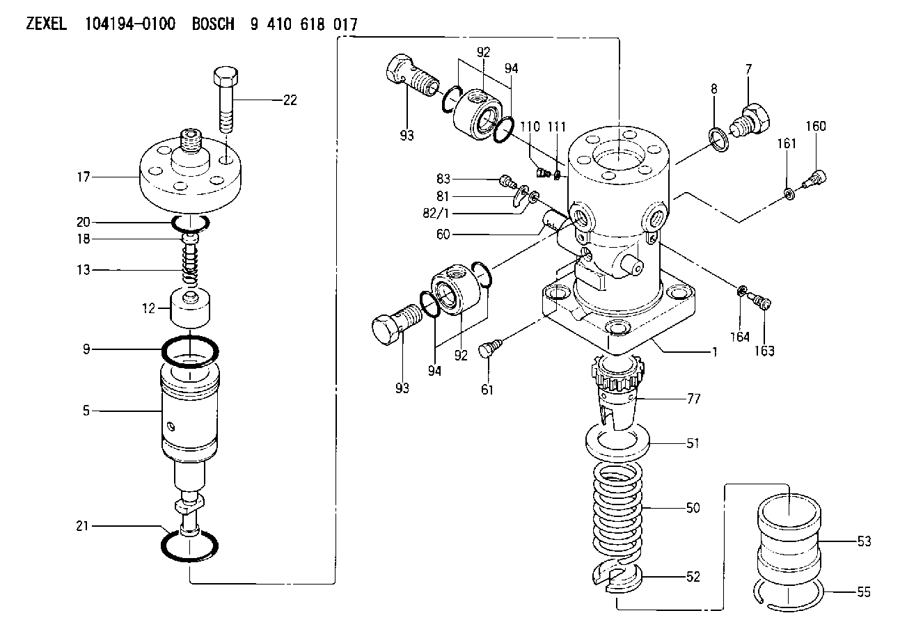
| 1. | [1] | 141054-7600 | PUMP HOUSING |
| 5. | [1] | 141157-2420 | PLUNGER-AND-BARREL ASSY |
| 7. | [1] | 141106-9600 | CAPSULE |
| 8. | [1] | 141403-2100 | GASKET |
| 9. | [1] | 141118-1600 | O-RING |
| 12. | [1] | 141140-6120 | DELIVERY-VALVE ASSEMBLY |
| 13. | [1] | 141112-5900 | COMPRESSION SPRING |
| 17. | [1] | 141136-3102 | FITTING |
| 18. | [1] | 141117-6801 | FILLER PIECE |
| 20. | [1] | 029635-4020 | O-RING &52W3 |
| 21. | [1] | 029637-5010 | O-RING |
| 22. | [6] | 141124-1100 | BLEEDER SCREW |
| 50. | [1] | 141215-4801 | COMPRESSION SPRING |
| 51. | [1] | 141216-1200 | SLOTTED WASHER |
| 52. | [1] | 141217-5000 | SLOTTED WASHER |
| 53. | [1] | 141218-7620 | GUIDE |
| 55. | [1] | 141220-0700 | LOCKING WASHER |
| 60. | [1] | 141244-4200 | CONTROL RACK |
| 61. | [1] | 141226-4700 | BLEEDER SCREW |
| 77. | [1] | 141292-1600 | CONTROL SLEEVE |
| 81. | [1] | 141245-3000 | POINTER |
| 82/1. | [0] | 023500-6210 | PLAIN WASHER D11&6.4T1.5 |
| 82/1. | [0] | 029300-6010 | PLAIN WASHER D11&6.4T0.8 |
| 82/1. | [0] | 029300-6020 | PLAIN WASHER D11&6.4T0.35 |
| 83. | [1] | 020006-1440 | BLEEDER SCREW M6P1L14 |
| 92. | [2] | 141401-2600 | INLET UNION |
| 92. | [2] | 141401-2600 | INLET UNION |
| 93. | [2] | 141402-3120 | EYE BOLT |
| 93. | [2] | 141402-3120 | EYE BOLT |
| 94. | [4] | 141403-0101 | O-RING |
| 94. | [4] | 141403-0101 | O-RING |
| 110. | [1] | 141420-0600 | BLEEDER SCREW |
| 111. | [1] | 141107-0500 | GASKET |
| 160. | [1] | 141418-1300 | SET OF NUTS |
| 161. | [1] | 141107-0800 | GASKET |
| 163. | [1] | 373658-1400 | CAPSULE |
| 164. | [1] | 026510-1340 | GASKET D13.4&10.2T1 |
Include in #1:
108822-2193
as _
Include in #2:
104194-0100
as INJECTION-PUMP ASSEMBLY
Cross reference number
Zexel num
Bosch num
Firm num
Name
104194-0100
FUEL-INJECTION PUMP
K 24JV FUEL INJECTION PUMP PF-1DV PF
K 24JV FUEL INJECTION PUMP PF-1DV PF
Information:
General Torque Information
Mismatched or incorrect fasteners can result in damage or malfunction, or possible injury.Take care to avoid mixing metric dimensioned fasteners and inch dimensioned fasteners.
Exceptions to these torques are given in the Service Manual, if necessary.Prior to installing any hardware, ensure that the components are in near new condition. Bolts and threads must nor be worn or damaged. Threads must not have burrs or nicks. Hardware must be free of rust and corrosion. Clean the hardware with a noncorrosive cleaner. Do not lubricate the fastener threads except with rust preventive. The rust preventive should be applied by the supplier of that component for purposes of shipping and storage. Other applications for lubricating components may also be specified in the Service Manual.For additional torque specifications, refer to SENR3130, Torque Specifications, available from your Caterpillar dealer.Standard Torque for Bolts, Nuts and Taperlock Studs
Torques for Taperlock Studs
Use these standard torque values for all fasteners unless otherwise specified in this manual or in the Service Manual.Torque for Metric Fasteners
Torque for Standard Hose Clamps-Worm Drive Band Type
The chart that follows gives the torques for initial installation of hose clamps on new hose and for reassembly or tightening of hose clamps on existing hose.
Torque for Constant Torque Hose Clamps
A constant torque hose clamp can be used in place of any standard hose clamp. Make sure the constant torque hose clamp is the same size as the standard clamp. Due to extreme temperature changes, hose will heat set. Heat setting causes hose clamps to loosen. Loose hose clamps can result in leaks. There have been reports of component failures caused by hose clamps loosening. The constant torque hose clamp will help prevent these failures. Use a torque wrench for proper installation of the constant torque hose clamp. The constant torque hose clamp is installed correctly under the following conditions: * Screw tip (1) extends 6.35 mm (.250 in) (X) beyond the housing.* The belleville washers are collapsed nearly flat after screw (2) is tightened to a torque of 11 1 N m (98 9 lb in).