Information fuel-injection pump
BOSCH
9 410 617 199
9410617199
ZEXEL
104193-0050
1041930050
Rating:
Components :
| 0. | INJECTION-PUMP ASSEMBLY | 104193-0050 |
| 1. | _ | |
| 2. | FUEL INJECTION PUMP | |
| 3. | NUMBER PLATE | |
| 4. | _ | |
| 5. | CAPSULE | |
| 6. | ADJUSTING DEVICE | |
| 7. | NOZZLE AND HOLDER ASSY | |
| 8. | Nozzle and Holder | |
| 9. | Open Pre:MPa(Kqf/cm2) | |
| 10. | NOZZLE-HOLDER | |
| 11. | NOZZLE |
Scheme ###:
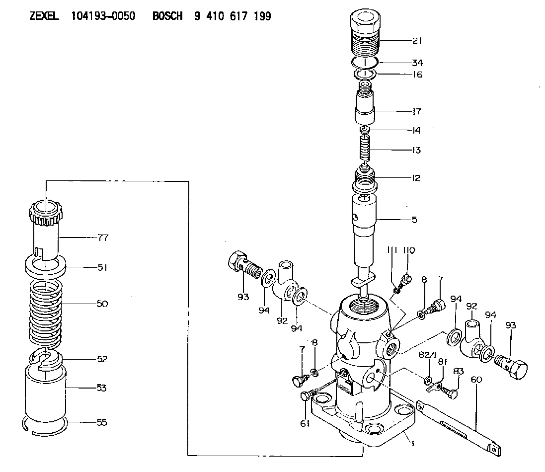
| 1. | [1] | 141053-0020 | PUMP HOUSING |
| 5. | [1] | 141172-0720 | PLUNGER-AND-BARREL ASSY D39 |
| 7. | [2] | 141106-8600 | CAPSULE |
| 7. | [2] | 141106-8600 | CAPSULE |
| 8. | [2] | 029331-2010 | GASKET |
| 8. | [2] | 029331-2010 | GASKET |
| 12. | [1] | 141110-3920 | DELIVERY-VALVE ASSEMBLY 7N14 |
| 12/1. | [1] | 141110-3900 | VALVE BODY |
| 13. | [1] | 141112-0201 | COMPRESSION SPRING |
| 14. | [1] | 141113-0300 | SLOTTED WASHER |
| 16. | [1] | 141115-4700 | GASKET |
| 17. | [1] | 141116-5500 | FITTING |
| 21. | [1] | 141119-1700 | NUT |
| 34. | [1] | 029636-5010 | O-RING |
| 50. | [1] | 141215-1400 | COMPRESSION SPRING |
| 51. | [1] | 141216-1200 | SLOTTED WASHER |
| 52. | [1] | 141217-3200 | SLOTTED WASHER |
| 53. | [1] | 141218-5520 | GUIDE |
| 55. | [1] | 141220-0700 | LOCKING WASHER |
| 60. | [1] | 141243-2000 | CONTROL RACK |
| 61. | [1] | 141226-3300 | BLEEDER SCREW |
| 77. | [1] | 141241-1700 | CONTROL SLEEVE |
| 81. | [1] | 141245-2000 | POINTER |
| 82/1. | [0] | 023500-6210 | PLAIN WASHER D11&6.4T1.5 |
| 82/1. | [0] | 029300-6010 | PLAIN WASHER D11&6.4T0.8 |
| 82/1. | [0] | 029300-6020 | PLAIN WASHER D11&6.4T0.35 |
| 83. | [1] | 020006-1440 | BLEEDER SCREW |
| 92. | [2] | 029702-6020 | INLET UNION |
| 92. | [2] | 029702-6020 | INLET UNION |
| 93. | [2] | 029732-6010 | EYE BOLT |
| 93. | [2] | 029732-6010 | EYE BOLT |
| 94. | [4] | 026526-3440 | GASKET |
| 94. | [4] | 026526-3440 | GASKET |
| 94. | [4] | 026526-3440 | GASKET |
| 94. | [4] | 026526-3440 | GASKET |
| 110. | [1] | 141420-1600 | BLEEDER SCREW |
| 111. | [1] | 026506-1040 | GASKET |
Include in #1:
101607-6611
as _
Include in #2:
104193-0050
as INJECTION-PUMP ASSEMBLY
Cross reference number
Zexel num
Bosch num
Firm num
Name
104193-0050
FUEL-INJECTION PUMP
K 24JA FUEL INJECTION PUMP PF-1DD(V) PF
K 24JA FUEL INJECTION PUMP PF-1DD(V) PF
Information:
Prior to stopping an engine that is being operated at low loads, run the engine at low idle for 30 seconds before stopping. But, if the engine is being operated at highway speeds and/or high loads, then it should be run at low idle for three minutes to reduce and stabilize internal engine temperature before stopping.To stop the engine, use the method listed that applies to the shutoff system on your truck.1. Turn the key switch to the OFF position, or2. ... pull OUT the manual shutoff control (if equipped), or3. ... push IN and hold the stop button until the engine stops, then release the button.Make sure the shutoff procedure is understood. Refer to the truck manufacturer's instructions for your type of engine shutoff system used. Fill the fuel tank at the end of each day of operation to drive out moist air and to prevent condensation. Do not fill the tank to the top. Fuel expands as it gets warm and may overflow.Manual Fuel Shutoff Lever
A manual shutdown lever is provided to override the governor control of the engine. The manual shutoff solenoid override lever is located on the side of the fuel pump. This shutdown will only move the fuel control linkage to the FUEL-OFF position. It does not shut off the air inlet. Shutoff Solenoid Override
The manual shutoff solenoid override lever is located on the side of the electronic governor. The engine can be shut OFF by rotating and holding the manual shutoff lever in the counterclockwise (CCW) direction. Rotating and holding the manual shutoff lever in the clockwise (CW) direction overrides the shutoff solenoid. The lever is spring loaded and will return to the neutral position when released.If the solenoid has been disabled, the engine cannot be shut OFF from inside the cab. The engine can be shut OFF by using the manual shutoff lever as an emergency shutoff lever.
DO NOT operate the engine without the rack actuator solenoid (BTM) in place and with the fuel shutoff solenoid disabled. Excessive engine speed (overspeed) may result.