Information fuel-injection pump
BOSCH
9 410 618 336
9410618336
ZEXEL
104190-0291
1041900291
Rating:
Components :
| 0. | INJECTION-PUMP ASSEMBLY | 104190-0291 |
| 1. | _ | |
| 2. | FUEL INJECTION PUMP | |
| 3. | NUMBER PLATE | |
| 4. | _ | |
| 5. | CAPSULE | |
| 6. | ADJUSTING DEVICE | |
| 7. | NOZZLE AND HOLDER ASSY | |
| 8. | Nozzle and Holder | |
| 9. | Open Pre:MPa(Kqf/cm2) | |
| 10. | NOZZLE-HOLDER | |
| 11. | NOZZLE |
Scheme ###:
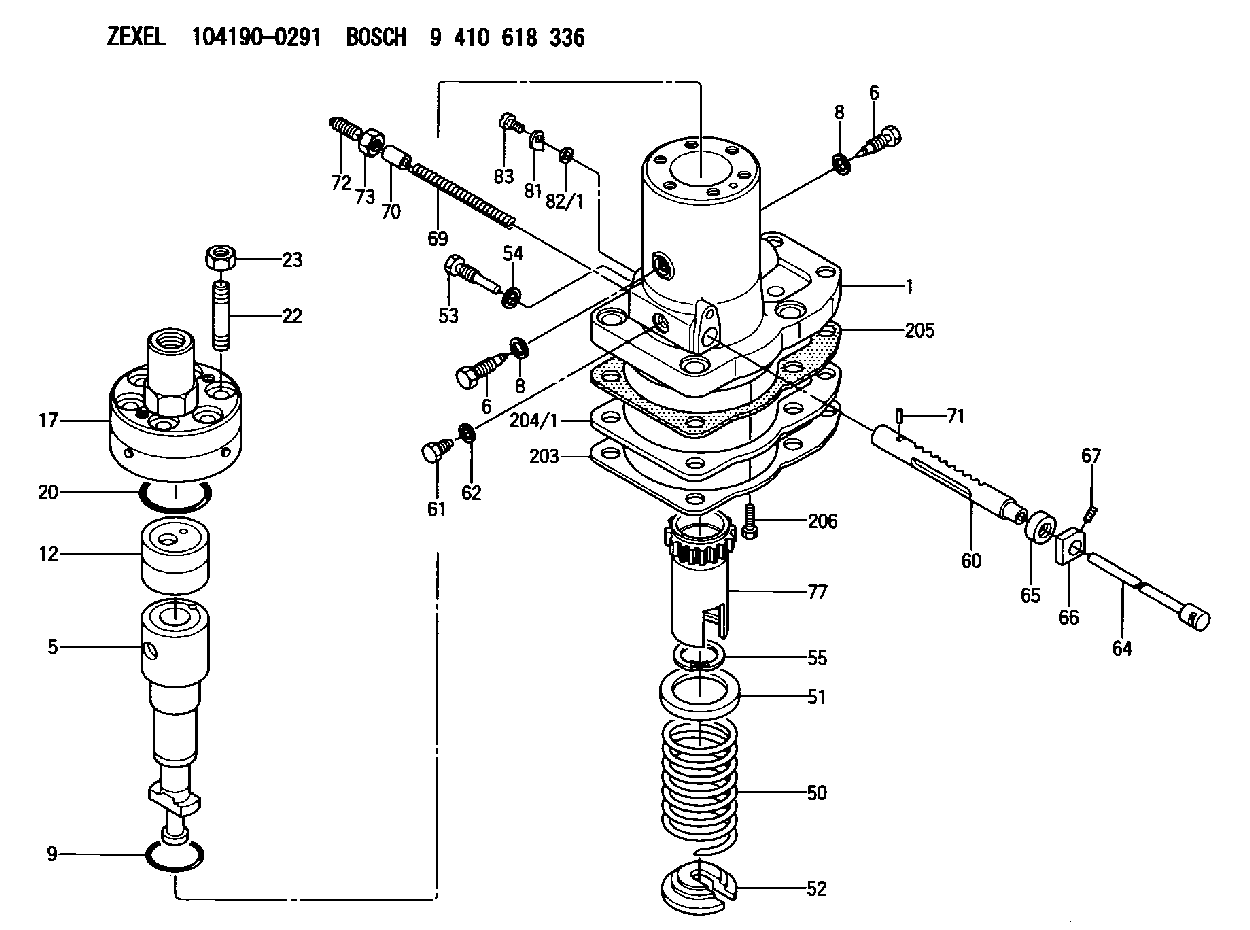
| 1. | [1] | 141052-6321 | PUMP HOUSING |
| 5. | [1] | 141154-3721 | PLUNGER-AND-BARREL ASSY |
| 6. | [2] | 141106-9400 | CAPSULE |
| 6. | [2] | 141106-9400 | CAPSULE |
| 8. | [2] | 029311-2030 | GASKET |
| 8. | [2] | 029311-2030 | GASKET |
| 9. | [1] | 029635-7040 | O-RING |
| 12. | [1] | 141140-4920 | DELIVERY-VALVE ASSEMBLY |
| 12/1. | [1] | 141140-4820 | DELIVERY-VALVE ASSEMBLY |
| 12/1/1. | [2] | 141110-7701 | DELIVERY-VALVE ASSEMBLY |
| 12/1/2. | [1] | 141141-0000 | SEAT;D.V. |
| 12/2. | [1] | 029405-0170 | BEARING PIN |
| 12/3. | [1] | 141112-2400 | COMPRESSION SPRING |
| 12/4. | [1] | 141112-4900 | COMPRESSION SPRING |
| 12/5. | [2] | 141450-0600 | PLATE |
| 12/6. | [2] | 141222-0600 | LOCKING WASHER |
| 17. | [1] | 141137-9520 | FITTING |
| 17/1. | [1] | 141137-9510 | FITTING |
| 20. | [1] | 141482-1900 | O-RING |
| 22. | [6] | 141120-0300 | STUD |
| 23. | [6] | 141121-0400 | UNION NUT |
| 50. | [1] | 141215-5700 | COMPRESSION SPRING |
| 51. | [1] | 141216-3800 | SLOTTED WASHER |
| 52. | [1] | 141217-6000 | SLOTTED WASHER |
| 53. | [1] | 141266-0000 | BLEEDER SCREW |
| 54. | [1] | 026510-1340 | GASKET D13.4&10.2T1 |
| 55. | [1] | 016110-4520 | LOCKING WASHER |
| 60. | [1] | 141244-2800 | CONTROL RACK |
| 61. | [1] | 141226-1600 | BLEEDER SCREW |
| 62. | [1] | 026510-1340 | GASKET D13.4&10.2T1 |
| 64. | [1] | 141239-0020 | RACK |
| 65. | [1] | 141268-0000 | FILLER PIECE |
| 66. | [1] | 141231-0000 | FILLER PIECE |
| 67. | [1] | 029100-6070 | SET OF NUTS |
| 69. | [1] | 141238-0000 | COILED SPRING |
| 70. | [1] | 141232-0100 | SLOTTED WASHER |
| 71. | [1] | 025640-1610 | BEARING PIN |
| 72. | [1] | 141267-0400 | FLAT-HEAD SCREW |
| 73. | [1] | 141439-2000 | UNION NUT |
| 77. | [1] | 141241-5200 | CONTROL SLEEVE |
| 81. | [1] | 141245-1800 | POINTER |
| 82/1. | [0] | 029310-6110 | SHIM D13.5&6.2T0.10 |
| 82/1. | [0] | 029310-6120 | SHIM D13.5&6.2T0.20 |
| 82/1. | [0] | 029310-6130 | SHIM D13.5&6.2T0.50 |
| 82/1. | [0] | 029310-6140 | SHIM D13.5&6.2T1.00 |
| 82/1. | [0] | 029310-6150 | SHIM D13.5&6.2T2.00 |
| 82/1. | [0] | 029310-6160 | SHIM D13.5&6.2T3.50 |
| 82/1. | [0] | 029310-6170 | SHIM D13.5&6.2T0.25 |
| 82/1. | [0] | 029310-6180 | SHIM D13.5&6.2T0.15 |
| 82/1. | [0] | 029310-6190 | SHIM D13.5&6.2T0.30 |
| 83. | [1] | 029060-6050 | FLAT-HEAD SCREW |
| 203. | [1] | 141488-1900 | SPACER BUSHING |
| 204/1. | [1] | 141488-0000 | SPACER BUSHING T3.05 |
| 204/1. | [1] | 141488-0100 | SPACER BUSHING T3.15 |
| 204/1. | [1] | 141488-0200 | SPACER BUSHING T3.25 |
| 204/1. | [1] | 141488-0300 | SPACER BUSHING T3.35 |
| 204/1. | [1] | 141488-0400 | SPACER BUSHING T3.45 |
| 204/1. | [1] | 141488-0500 | SPACER BUSHING T3.55 |
| 205. | [1] | 141489-0000 | GASKET |
| 206. | [2] | 029030-5080 | BLEEDER SCREW |
Include in #1:
101401-1870
as _
Include in #2:
104190-0291
as INJECTION-PUMP ASSEMBLY
Cross reference number
Zexel num
Bosch num
Firm num
Name
104190-0291
9 410 618 336
FUEL-INJECTION PUMP
K 24MB FUEL INJECTION PUMP PF-MAN 40/54A PF
K 24MB FUEL INJECTION PUMP PF-MAN 40/54A PF
Information:
Water Pump Seal
Over concentration of coolant additive (Conditioner), mineral deposits from hard water or cooling system contamination can accelerate the wear on the water pump coolant seal. The cooling system maintenance interval provides an opportunity to inspect and replace the water pump seal if necessary to reduce coolant leakage.Dispose of used engine coolant in an environmentally correct way or recycle. Various methods have been proposed to reclaim used coolant for reuse in engine cooling systems. The full distillation procedure is the only method acceptable by Caterpillar to reclaim the used coolant and for information regarding disposal and recycling of used coolant.4. Clean and install all drain plugs and/or close the cooling system drain valve(s).Replace Thermostat, Gaskets and Seal
Refer to the Service Manual for detailed instructions regarding Disassembly and Assembly of the Cooling System. Repeat procedure for both thermostat housing assemblies.Replacing the thermostats prior to failure is a recommended preventive maintenance practice because it reduces the chances for cooling system problems and unscheduled downtime.
Failure to replace your thermostats on a regularly scheduled basis could cause severe engine damage.
If replacing thermostats ONLY, drain the coolant from the cooling system to a level below the thermostat housing.5. Disconnect hose assemblies from radiator and each thermostat housing assembly.6. Remove bolts and thermostat housing assembly.7. Remove the gasket, thermostat and seal from each housing.
Former thermostats may be used, if they meet test specifications as described in the Service Manual (and are not damaged or have excessive buildup of deposits).
The thermostats can be reused if they are tested and meet the test specifications in the Service Manual.Flush
8. Refill the cooling system with clean water mixed with the proper concentration (six to ten percent) of Fast Acting-Type Caterpillar Cooling System Cleaner (4C4611). Tighten cooling system vent cap. For proper cooling system maintenance cleaning, refer to label directions for the type of Caterpillar Cooling System Cleaner used in your cooling system.9. Start and run (operate) the engine to circulate fluid in the cooling system.10. Stop the engine and allow to cool. Loosen cooling system vent cap and drain plugs.11. Drain the cleaning solution. Flush the cooling system with clean water and a neutralizing solution until draining water is clear. Clean and install all drain plugs and/or close the drain valve. Sodium Carbonate crystals at a rate of 250 grams per 40 liters of water (1/2 pound per 10 U.S. gallon of water) may be used as a neutralizer. Repeat Steps 8 thru 11 if necessary until the draining water is clear.Install Thermostat
Caterpillar engines incorporate a shunt design cooling system and require operating the engine with a thermostat installed.If the thermostat is installed wrong, it will cause the engine to overheat.
Inspect gaskets before assembly and replace if worn or damaged.12. Install a new seal in each thermostat housing and install new thermostats.13. Install a new gasket and the thermostat housing on the engine cylinder head.14. Install the cooling system connections and tighten the hose or piping clamps.Fill
All water is corrosive at engine operating temperature. The cooling system
Have questions with 104190-0291?
Group cross 104190-0291 ZEXEL
Kawasaki-Heavy
M.Bishi.Hi.Yoko
M.Bishi.Hi.Yoko
104190-0291
9 410 618 336
FUEL-INJECTION PUMP