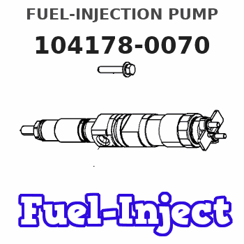
Information fuel-injection pump
BOSCH
9 410 617 801
9410617801
ZEXEL
104178-0070
1041780070
AKASAKA-DIESEL
A31N152701
a31n152701
Rating:
Components :
| 0. | INJECTION-PUMP ASSEMBLY | 104178-0070 |
| 1. | _ | |
| 2. | FUEL INJECTION PUMP | |
| 3. | NUMBER PLATE | |
| 4. | _ | |
| 5. | CAPSULE | |
| 6. | ADJUSTING DEVICE | |
| 7. | NOZZLE AND HOLDER ASSY | |
| 8. | Nozzle and Holder | |
| 9. | Open Pre:MPa(Kqf/cm2) | |
| 10. | NOZZLE-HOLDER | |
| 11. | NOZZLE |
Scheme ###:
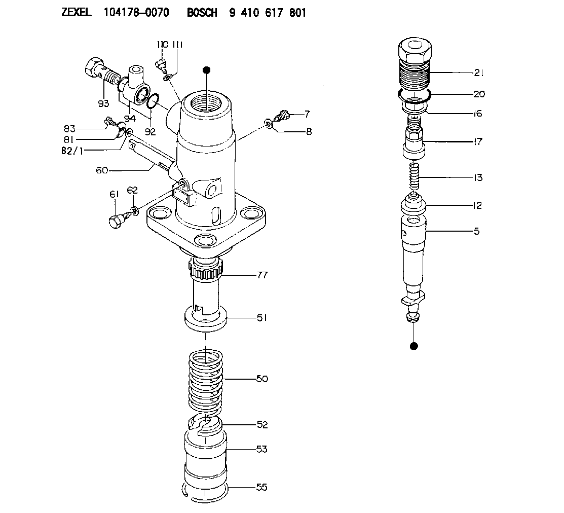
| 5. | [1] | 141172-6520 | PLUNGER-AND-BARREL ASSY |
| 7. | [1] | 141106-8800 | CAPSULE |
| 8. | [1] | 029331-2010 | GASKET |
| 12. | [1] | 141110-3720 | DELIVERY-VALVE ASSEMBLY |
| 13. | [1] | 141112-0201 | COMPRESSION SPRING |
| 16. | [1] | 141115-4100 | GASKET |
| 17. | [1] | 141126-4720 | FITTING |
| 20. | [1] | 141118-0100 | O-RING |
| 21. | [1] | 141119-1400 | NUT |
| 50. | [1] | 141215-1200 | COMPRESSION SPRING |
| 51. | [1] | 141216-0900 | SLOTTED WASHER |
| 52. | [1] | 141217-3300 | SLOTTED WASHER |
| 53. | [1] | 141218-5720 | GUIDE |
| 55. | [1] | 141220-0500 | LOCKING WASHER |
| 60. | [1] | 141243-2900 | CONTROL RACK |
| 61. | [1] | 141226-3400 | BLEEDER SCREW |
| 62. | [1] | 029331-0010 | GASKET |
| 77. | [1] | 141241-3400 | CONTROL SLEEVE |
| 81. | [1] | 141245-2400 | POINTER |
| 82/1. | [0] | 023500-6210 | PLAIN WASHER D11&6.4T1.5 |
| 82/1. | [0] | 029300-6010 | PLAIN WASHER D11&6.4T0.8 |
| 82/1. | [0] | 029300-6020 | PLAIN WASHER D11&6.4T0.35 |
| 83. | [1] | 020006-1440 | BLEEDER SCREW M6P1L14 |
| 92. | [1] | 141401-0800 | INLET UNION |
| 93. | [1] | 141402-0200 | EYE BOLT |
| 94. | [2] | 029633-5051 | O-RING |
| 110. | [1] | 141420-0100 | BLEEDER SCREW |
| 111. | [1] | 026508-1240 | GASKET D11.9&8.2T1 |
Cross reference number
Zexel num
Bosch num
Firm num
Name
104178-0070
A31N152701 AKASAKA-DIESEL
FUEL-INJECTION PUMP
K 24KA FUEL INJECTION PUMP PF-ED PF
K 24KA FUEL INJECTION PUMP PF-ED PF
Information:
A measurement of fuel consumption is used to check fuel system performance. If fuel consumption of an engine is within the tolerance of specifications shown in the FUEL SETTING AND RELATED INFORMATION FICHE, the fuel system is performing correctly and no additional time should be spent checking fuel delivery.Fuel consumption - If the specified amount of fuel is being injected into the engine, the fuel delivery specification is being met. Therefore, the basic fuel system (fuel pump and lines, transfer pump, filters and primary fuel pressure) is within functional limits. Additional time spent troubleshooting these components is probably not justified.Fuel system timing - Fuel can not be burned efficiently if it is not injected into the cylinder at the correct time. Because engines only develop horsepower when they are running, timing must be measured when they are running. The pin timing of the engine is not adequate. Timing must be measured throughout the speed range (this also checks the timing advance operation).Intake manifold pressure - Manifold pressure is an indication of the overall health of the engine. Boost is affected by any one or all of the following: Fuel consumption, Compression (valve condition, piston ring condition), Turbocharger performance, Intake restriction (air filters), Exhaust restriction (muffler), or Timing.Recommended Procedure With Chassis Dynamometer
Possible Causes/Corrections
1. Check Records Used To Determine Fuel Consumption/Make sure the records are accurate. The minimum period for accurate fuel records is one month or 10,000 miles. Check the tires (air pressure and size), the gap between the tractor and trailer, air deflectors, trailer width, trailer type, engine cooling fan and driver habits. See OWNER/OPERATOR INPUT section for more information on the questions that should be asked.2. Minor Operating Faults/To help identify a problem before a more involved troubleshooting procedure is started, follow the procedure given in the PRIMARY ENGINE CHECKS section.3. Fuel Ratio Control Out of Adjustment or Bad/Follow the procedure in the Testing and Adjusting section of this Service Manual.4. Check Engine Performance/Do a Power Analysis Report (PAR), Level II, to check engine performance. See Special Instruction, Form No. SEHS8025 and SEHS7886 for the tooling and procedures to use. Be sure to make a record of the temperatures for inlet air, fuel (at filter base), lubricating oil and coolant. Also, check for excessive exhaust smoke. At this point, the governor fuel settings should be verified. See the Testing and Adjusting section of this Service Manual for the correct procedures to use. Also refer back to the information learned earlier (see OWNER/OPERATOR INPUT section) about truck specifications and application and judge whether or not the engine is performing as expected or customer expectation is realistic.5. Worn Fuel Nozzles/Check the horsepower on a dynamometer as in Step 4 above. Make a replacement of the fuel injection nozzles and check the horsepower output again. If there is more than 10 hp difference the old nozzles had eroded orifices and were causing high fuel rate. An alternate test is to lower the fuel setting to get the correct hp output.