Information fuel-injection pump
BOSCH
9 410 617 800
9410617800
ZEXEL
104177-0020
1041770020
AKASAKA-DIESEL
A33N152701
a33n152701

Rating:
Components :
| 0. | INJECTION-PUMP ASSEMBLY | 104177-0020 |
| 1. | _ | |
| 2. | FUEL INJECTION PUMP | |
| 3. | NUMBER PLATE | |
| 4. | _ | |
| 5. | CAPSULE | |
| 6. | ADJUSTING DEVICE | |
| 7. | NOZZLE AND HOLDER ASSY | |
| 8. | Nozzle and Holder | |
| 9. | Open Pre:MPa(Kqf/cm2) | |
| 10. | NOZZLE-HOLDER | |
| 11. | NOZZLE |
Scheme ###:
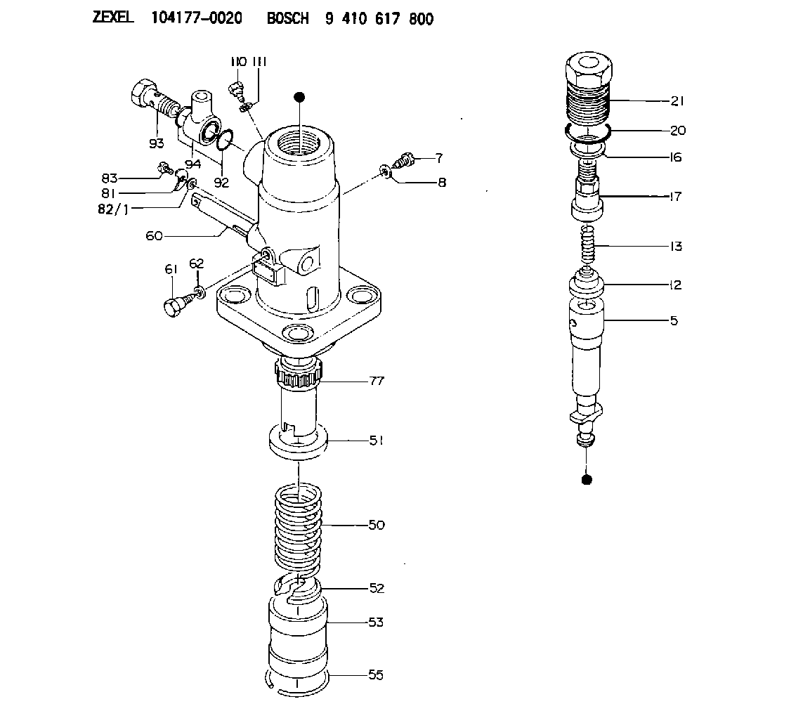
| 5. | [1] | 141172-6320 | PLUNGER-AND-BARREL ASSY |
| 7. | [1] | 141106-8800 | CAPSULE |
| 8. | [1] | 029331-2010 | GASKET |
| 12. | [1] | 141110-3720 | DELIVERY-VALVE ASSEMBLY |
| 13. | [1] | 141112-0201 | COMPRESSION SPRING |
| 16. | [1] | 141115-4100 | GASKET |
| 17. | [1] | 141126-4720 | FITTING |
| 20. | [1] | 141118-0100 | O-RING |
| 21. | [1] | 141119-1400 | NUT |
| 50. | [1] | 141215-1200 | COMPRESSION SPRING |
| 51. | [1] | 141216-0900 | SLOTTED WASHER |
| 52. | [1] | 141217-3300 | SLOTTED WASHER |
| 53. | [1] | 141218-5720 | GUIDE |
| 55. | [1] | 141220-0500 | LOCKING WASHER |
| 60. | [1] | 141243-2900 | CONTROL RACK |
| 61. | [1] | 141226-3400 | BLEEDER SCREW |
| 62. | [1] | 029331-0010 | GASKET |
| 77. | [1] | 141241-3400 | CONTROL SLEEVE |
| 81. | [1] | 141245-2400 | POINTER |
| 82/1. | [0] | 023500-6210 | PLAIN WASHER D11&6.4T1.5 |
| 82/1. | [0] | 029300-6010 | PLAIN WASHER D11&6.4T0.8 |
| 82/1. | [0] | 029300-6020 | PLAIN WASHER D11&6.4T0.35 |
| 83. | [1] | 020006-1440 | BLEEDER SCREW M6P1L14 |
| 92. | [1] | 141401-0800 | INLET UNION |
| 93. | [1] | 141402-0200 | EYE BOLT |
| 94. | [2] | 029633-5051 | O-RING |
| 110. | [1] | 141420-0100 | BLEEDER SCREW |
| 111. | [1] | 026508-1240 | GASKET D11.9&8.2T1 |
Cross reference number
Zexel num
Bosch num
Firm num
Name
104177-0020
A33N152701 AKASAKA-DIESEL
FUEL-INJECTION PUMP
K 24KA FUEL INJECTION PUMP PF-ED PF
K 24KA FUEL INJECTION PUMP PF-ED PF
Information:
Starter Motor
The starter motor is used to turn the engine flywheel fast enough to get the engine to start running.The starter motor has a solenoid. When the start switch is activated, the solenoid will move the starter pinion to engage it with the ring gear on the flywheel of the engine. The starter pinion will engage with the ring gear before the electric contacts in the solenoid close the circuit between the battery and the starter motor. When the circuit between the battery and the starter motor is complete, the pinion will turn the engine flywheel. A clutch gives protection for the starter motor so that the engine cannot turn the starter motor too fast. When the start switch is released, the starter pinion will move away from the ring gear.
Starter Motor Cross Section
(1) Field. (2) Solenoid. (3) Clutch. (4) Pinion. (5) Commutator. (6) Brush assembly. (7) Armature.Other Components
Circuit Breaker
Circuit Breaker Schematic
(1) Reset button. (2) Disc in open position. (3) Contacts. (4) Disc. (5) Battery circuit terminals.The circuit breaker is a switch that opens the battery circuit if the current in the electrical system goes higher than the rating of the circuit breaker.A heat activated metal disc with a contact point makes complete the electric circuit through the circuit breaker. If the current in the electrical system gets too high, it causes the metal disc to get hot. This heat causes a distortion of the metal disc which opens the contacts and breaks the circuit. A circuit breaker that is open can be reset (an adjustment to make the circuit complete again) after it becomes cool. Push the reset button to close the contacts and reset the circuit breaker.Jake Brake
The JAKE BRAKE permits the operator to control the speed of the vehicle on grades, curves, or anytime when speed reduction is necessary, but long applications of the service brakes are not desired. In downhill operation, or any slow down condition, the engine crankshaft is turned by the rear wheels (through the differential, driveshaft, transmission and clutch). To reduce the speed of the vehicle, an application of a braking force can be made to the pistons of the engine.The JAKE BRAKE, when activated, does this through the conversion of the engine from a source of power to an air compressor that absorbs (takes) power. This conversion is made possible by a master to slave piston arrangement, where movement of the rocker arm for the exhaust valve of one cylinder is transferred hydraulically to open the exhaust valve of another cylinder near the top of its normal compression stroke cycle. The compressed cylinder charge is now released into the exhaust manifold.The release of the compressed air pressure to the atmosphere prevents the return of energy to the engine piston on the expansion (power) stroke. The result is an energy loss, since the work done by the compression of the cylinder charge is not returned by the expansion process. This energy loss is taken from the rear wheels, which provides the