Information fuel-injection pump
BOSCH
9 410 617 384
9410617384
ZEXEL
104147-0033
1041470033
MITSUBISHI-HEAV
4106504000
4106504000

Rating:
Components :
| 0. | INJECTION-PUMP ASSEMBLY | 104147-0033 |
| 1. | _ | |
| 2. | FUEL INJECTION PUMP | |
| 3. | NUMBER PLATE | |
| 4. | _ | |
| 5. | CAPSULE | |
| 6. | ADJUSTING DEVICE | |
| 7. | NOZZLE AND HOLDER ASSY | 105193-3043 |
| 8. | Nozzle and Holder | |
| 9. | Open Pre:MPa(Kqf/cm2) | 34.3{350} |
| 10. | NOZZLE-HOLDER | 105093-6004 |
| 11. | NOZZLE | 105011-9630 |
Scheme ###:
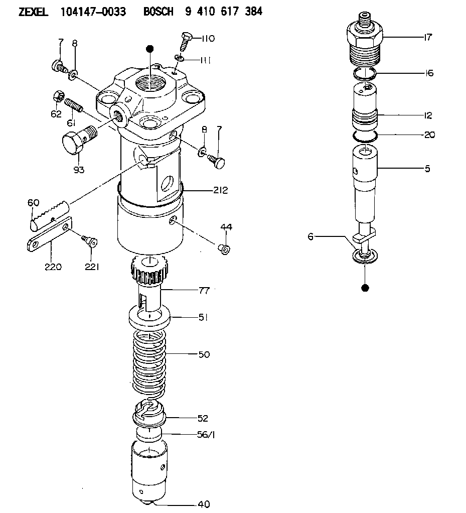
| 5. | [1] | 141175-0020 | PLUNGER-AND-BARREL ASSY |
| 6. | [1] | 141162-0000 | GASKET |
| 7. | [2] | 141133-0300 | CAPSULE |
| 7. | [2] | 141133-0300 | CAPSULE |
| 8. | [2] | 029331-0020 | GASKET |
| 8. | [2] | 029331-0020 | GASKET |
| 12. | [1] | 141142-6221 | DELIVERY-VALVE ASSEMBLY |
| 16. | [1] | 141115-5700 | GASKET |
| 17. | [1] | 141137-1500 | FITTING |
| 20. | [1] | 029633-2040 | O-RING |
| 40. | [1] | 141200-2420 | TAPPET |
| 44. | [1] | 141212-0300 | BEARING PIN |
| 50. | [1] | 141215-5100 | COMPRESSION SPRING |
| 51. | [1] | 141216-3400 | SLOTTED WASHER |
| 52. | [1] | 141217-5200 | SLOTTED WASHER |
| 56/1. | [1] | 141254-0700 | PLATE T7.3 |
| 56/1. | [1] | 141254-0800 | PLATE T7.6 |
| 56/1. | [1] | 141254-0900 | PLATE T7.9 |
| 56/1. | [1] | 141254-1000 | PLATE T8.2 |
| 56/1. | [1] | 141254-1100 | PLATE T8.5 |
| 60. | [1] | 141244-4501 | CONTROL RACK |
| 61. | [1] | 141267-0500 | FLAT-HEAD SCREW |
| 62. | [1] | 013020-8140 | UNION NUT M8P1.25H6.5 |
| 77. | [1] | 141241-6800 | CONTROL SLEEVE |
| 93. | [1] | 141402-2100 | EYE BOLT |
| 110. | [1] | 141420-0700 | BLEEDER SCREW |
| 111. | [1] | 141403-1400 | GASKET |
| 212. | [1] | 141482-2400 | O-RING |
| 220. | [1] | 141260-1600 | CONTROL LEVER |
| 221. | [1] | 141282-0300 | FLAT-HEAD SCREW |
Cross reference number
Zexel num
Bosch num
Firm num
Name
104147-0033
9 410 617 384
4106504000 MITSUBISHI-HEAV
FUEL-INJECTION PUMP
* K
* K
Information:
START BY:a. remove alternator and mounting groupb. remove water temperature regulator and manifold1. Drain the coolant from the engine. 2. Loosen the clamps on breather tube (1), and pull it back for clearance. 3. Remove bolt (2) from the cover on the side of the cylinder block. 4. Remove the three bolts that hold cover (3) to the water pump. Remove cover (3) from the water pump. 5. Remove the two bolts, and remove elbow (4) from bonnet (5). Remove the two bolts, and remove bonnet (5) from the water pump. It is not necessary to remove bolts (6). These bolts only hold the cover to the timing gear cover.6. Remove six long bolts (7) that hold the water pump to the timing gear cover. Remove water pump (8).Install Water Pump
1. Check the O-ring seals and gaskets, and make replacements if needed. 2. Make sure O-ring seal (1) is in position on the water pump. Put water pump (2) into position in the timing gear cover. Install the bolts that hold the water pump in place. 3. Make sure the gaskets are in place. Connect bonnet (3) to the water pump. Connect elbow (4) to the bonnet. 4. Make sure O-ring seal (5) is in position, and install cover (6) on the water pump. 5. Install bolt (7) on the cover on the side of the engine. 6. Put breather tube (8) in position, and install the clamps that hold it.7. Fill the cooling system to the correct level. See the Maintenance Guide.Disassemble Water Pump
START BY:a. remove water pump The water pump seal can be replaced without removing the water pump from the engine.An intermittent leakage of a small amount of coolant from the hole in the water pump housing is not an indication of a water pump seal failure. This is required to provide lubrication for the seal. Replace the water pump seal only if a large amount of leakage or a constant flow of coolant is observed draining from the water pump housing.1. Remove O-ring seal (1) from the adapter.2. Remove adapter (2) from the housing. Remove the O-ring seal from the outside diameter of the adapter.3. Remove bolt (3) and the retainer that hold the impeller on the shaft. 4. Use tooling (A) to remove impeller (4) from the shaft. 5. Remove the spring and seal (5) from the shaft. 6. Remove four bolts (7) from retainer (6) that hold the shaft assembly to the pump housing.7. Remove O-ring seal (8) from the housing. 8. Remove gear and shaft assembly (10) from the housing.9. Remove bolt (9) and the retainer from the shaft assembly. 10. Use a press to remove the shaft assembly from gear (11). Remove the retainer from the shaft assembly. 11. Remove bearing (13), spacer (14) and bearing (12) from the shaft. 12. Remove lip-type seal (15) from the housing.13. Turn the housing over, and remove ceramic ring (16) and the seal.Assemble Water Pump
1. Use 6V1541 Quick Cure Primer and clean shaft
Have questions with 104147-0033?
Group cross 104147-0033 ZEXEL
Mitsubishi-Heav
Mitsubishi-Heav
104147-0033
9 410 617 384
4106504000
FUEL-INJECTION PUMP