Information fuel-injection pump
BOSCH
9 410 617 179
9410617179
ZEXEL
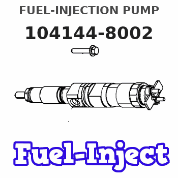
104144-8002
1041448002
DAIHATSU
339403Z
339403z
Rating:
Components :
| 0. | INJECTION-PUMP ASSEMBLY | 104144-8002 |
| 1. | _ | |
| 2. | FUEL INJECTION PUMP | |
| 3. | NUMBER PLATE | |
| 4. | _ | |
| 5. | CAPSULE | |
| 6. | ADJUSTING DEVICE | |
| 7. | NOZZLE AND HOLDER ASSY | |
| 8. | Nozzle and Holder | |
| 9. | Open Pre:MPa(Kqf/cm2) | |
| 10. | NOZZLE-HOLDER | |
| 11. | NOZZLE |
Scheme ###:
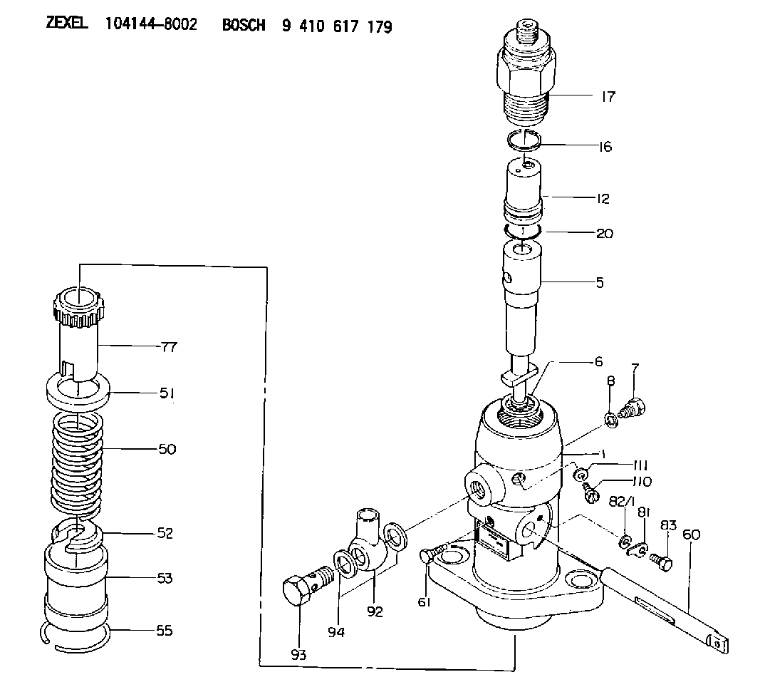
| 1. | [1] | 141052-7201 | PUMP HOUSING |
| 5. | [1] | 141175-2520 | PLUNGER-AND-BARREL ASSY |
| 6. | [1] | 029333-3010 | GASKET |
| 7. | [1] | 141133-3100 | CAPSULE |
| 8. | [1] | 029331-8010 | GASKET |
| 12. | [1] | 141142-6221 | DELIVERY-VALVE ASSEMBLY |
| 16. | [1] | 141115-6000 | GASKET |
| 17. | [1] | 141136-9000 | FITTING |
| 20. | [1] | 029633-2040 | O-RING |
| 50. | [1] | 141215-0700 | COMPRESSION SPRING |
| 51. | [1] | 141216-2400 | SLOTTED WASHER |
| 52. | [1] | 141217-0300 | SLOTTED WASHER |
| 53. | [1] | 141218-4500 | GUIDE |
| 55. | [1] | 141220-0300 | LOCKING WASHER |
| 60. | [1] | 142223-0200 | CONTROL RACK |
| 61. | [1] | 141226-3000 | BLEEDER SCREW |
| 77. | [1] | 141241-0900 | CONTROL SLEEVE |
| 81. | [1] | 141245-2000 | POINTER |
| 82/1. | [0] | 023500-6210 | PLAIN WASHER D11&6.4T1.5 |
| 82/1. | [0] | 029300-6010 | PLAIN WASHER D11&6.4T0.8 |
| 82/1. | [0] | 029300-6020 | PLAIN WASHER D11&6.4T0.35 |
| 83. | [1] | 020006-1440 | BLEEDER SCREW M6P1L14 |
| 92. | [1] | 027118-1540 | INLET UNION |
| 93. | [1] | 029731-8200 | EYE BOLT |
| 94. | [2] | 141403-0400 | GASKET |
| 110. | [1] | 140420-1600 | BLEEDER SCREW |
| 111. | [1] | 141421-0000 | GASKET |
Cross reference number
Zexel num
Bosch num
Firm num
Name
104144-8002
339403Z DAIHATSU
FUEL-INJECTION PUMP
K 24DA FUEL INJECTION PUMP PF-1C(D) PF
K 24DA FUEL INJECTION PUMP PF-1C(D) PF
104144-8002
339403Z DAIHATSU
FUEL-INJECTION PUMP
K 24DA FUEL INJECTION PUMP PF-1C(D) PF
K 24DA FUEL INJECTION PUMP PF-1C(D) PF
Information:
1. Disconnect fuel line (1) from the fuel transfer pump. Disconnect fuel line (2) from the fuel injection pump housing. Remove line (3) from the fuel ratio control and aftercooler housing. 2. Disconnect fuel injection lines (4) from the fuel injection pump housing.
Do not disconnect the air line from the air compressor governor until the air pressure is zero.
3. Loosen the bleed valves, and release the air pressure in the air tank. 4. Remove air line (5). Remove coolant line (6). 5. The weight of the fuel injection pump housing and governor is 57 kg (125 lb.). Attach a hoist to the fuel injection pump housing, and remove bolts (7). 6. Remove the two nuts and two bolts (8) and bolt (9). Remove fuel injection pump housing and governor (10). 7. Remove O-ring seals (11) from the fuel injection pump housing.Install Fuel Injection Pump Housing And Governor
1. Attach a hoist to the fuel injection pump housing and governor (1). Be sure that the three O-ring seals are in position in the fuel injection pump housing. Install the fuel injection pump housing and governor on the timing gear housing. 2. Connect air line (2) and water line (3) to the air compressor. 3. Connect fuel injection lines (4) to fuel injection pump housing, and tighten the fuel injection line nuts to a torque of 40 7 N m (30 5 lb.ft.) with tool (C). 4. Connect fuel line (5) to fuel injection pump housing, and connect fuel line (6) to the fuel transfer pump. Install line (7) between the fuel ratio control and aftercooler housing. For timing of the fuel injection pump, see Install Automatic Timing Advance.END BY:a. install automatic timing advance