Information fuel-injection pump
BOSCH
9 410 618 055
9410618055
ZEXEL
104144-3390
1041443390
Rating:
Components :
| 0. | INJECTION-PUMP ASSEMBLY | 104144-3390 |
| 1. | _ | |
| 2. | FUEL INJECTION PUMP | |
| 3. | NUMBER PLATE | |
| 4. | _ | |
| 5. | CAPSULE | |
| 6. | ADJUSTING DEVICE | |
| 7. | NOZZLE AND HOLDER ASSY | |
| 8. | Nozzle and Holder | |
| 9. | Open Pre:MPa(Kqf/cm2) | |
| 10. | NOZZLE-HOLDER | |
| 11. | NOZZLE |
Scheme ###:
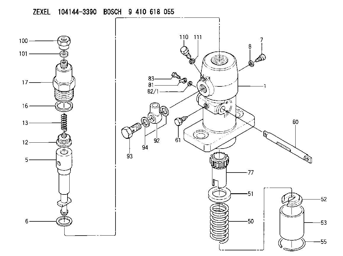
| 1. | [1] | 141051-7900 | PUMP HOUSING |
| 5. | [1] | 141170-1720 | PLUNGER-AND-BARREL ASSY |
| 6. | [1] | 141162-0000 | GASKET |
| 7. | [1] | 141106-8000 | CAPSULE |
| 8. | [1] | 029340-8020 | GASKET |
| 12. | [1] | 141110-6820 | DELIVERY-VALVE ASSEMBLY |
| 13. | [1] | 141112-0600 | COMPRESSION SPRING |
| 16. | [1] | 141115-0600 | GASKET |
| 17. | [1] | 141137-3000 | FITTING |
| 50. | [1] | 141215-0700 | COMPRESSION SPRING |
| 51. | [1] | 141216-2400 | SLOTTED WASHER |
| 52. | [1] | 141217-0300 | SLOTTED WASHER |
| 53. | [1] | 141218-4200 | GUIDE |
| 55. | [1] | 141220-0300 | LOCKING WASHER |
| 60. | [1] | 141230-7600 | CONTROL RACK |
| 61. | [1] | 141226-3100 | BLEEDER SCREW |
| 77. | [1] | 141241-0900 | CONTROL SLEEVE |
| 81. | [1] | 141245-2000 | POINTER |
| 82/1. | [0] | 023500-6210 | PLAIN WASHER D11&6.4T1.5 |
| 82/1. | [0] | 029300-6010 | PLAIN WASHER D11&6.4T0.8 |
| 82/1. | [0] | 029300-6020 | PLAIN WASHER D11&6.4T0.35 |
| 83. | [1] | 020006-1440 | BLEEDER SCREW M6P1L14 |
| 92. | [1] | 027118-1540 | INLET UNION |
| 93. | [1] | 029731-8200 | EYE BOLT |
| 94. | [2] | 026518-2240 | GASKET D21.9&18.2T1 |
| 100. | [1] | 029761-8190 | UNION NUT |
| 101. | [1] | 029351-0080 | PLAIN WASHER |
| 110. | [1] | 140420-1600 | BLEEDER SCREW |
| 111. | [1] | 026506-1040 | GASKET D9.9&6.2T1 |
Cross reference number
Zexel num
Bosch num
Firm num
Name
104144-3390
FUEL-INJECTION PUMP
K 24DA FUEL INJECTION PUMP PF-1C(D) PF
K 24DA FUEL INJECTION PUMP PF-1C(D) PF
Information:
1. Remove nuts (1). Remove cover (2) from the timing gear cover. 2. Remove bolts (3), and remove automatic timing advance (4). 3. Remove gear (5) from the front timing gear cover. The following steps are for installation of the automatic timing advance. 4. Lubricate seals (6) with clean engine oil. 5. Put gear (5) in position in the front timing gear cover. 6. Install two 3/8"-16 NC × 6" in. (152.4 mm) long guide bolts (7) in gear (5) as shown. 7. Install automatic timing advance (4) on the end of the fuel injection pump camshaft, and install bolts (3) that hold it. Tighten bolts (3) to a torque of 3 N m (27 lb.in.). 8. Put the No. 1 piston at top center on the compression stroke. Make reference to Finding Top Center Compression Position For No. 1 Piston in Testing And Adjusting. Remove the timing bolt from the flywheel, and use tool (A) to rotate the crankshaft clockwise (opposite the direction of engine rotation) 45°. 9. Remove plug (8) from the fuel injection pump housing. 10. Install tool (B) in the fuel injection pump housing as shown. Slowly rotate the crankshaft counterclockwise (direction of engine rotation) until the timing pin goes into the slot in the fuel injection pump camshaft.
Too much pressure on the timing pin can damage the fuel injection pump or the timing pin.
11. Put the timing bolt in the timing hole in the flywheel housing. Rotate the crankshaft counterclockwise (as seen from the flywheel end of the engine) until the fuel pump camshaft is tight against timing pin (2). This removes gear clearance from the drive train. If the bolt can be installed in the timing hole in the flywheel, the timing of the fuel injection pump is correct.12. If the timing bolt does not go into the timing hole in the flywheel, the timing is not correct. Do the steps that follow to adjust the fuel injection pump timing.a. Loosen four bolts (3). With tool (B) installed and the timing bolt removed, turn the flywheel clockwise (opposite the direction of engine rotation) a minimum of 45°. The reason for this step is to remove backlash from the timing gears when the engine is put on top center (TC).b. Tighten two bolts (3) 180° apart, evenly to a torque of 3 N m (27 lb.in.).c. Turn the flywheel slowly