Information fuel-injection pump
BOSCH
9 410 618 168
9410618168
ZEXEL
104144-3160
1041443160
1C947004A
Rating:
Components :
| 0. | INJECTION-PUMP ASSEMBLY | 104144-3160 |
| 1. | _ | |
| 2. | FUEL INJECTION PUMP | |
| 3. | NUMBER PLATE | |
| 4. | _ | |
| 5. | CAPSULE | |
| 6. | ADJUSTING DEVICE | |
| 7. | NOZZLE AND HOLDER ASSY | |
| 8. | Nozzle and Holder | |
| 9. | Open Pre:MPa(Kqf/cm2) | |
| 10. | NOZZLE-HOLDER | 105033-6410 |
| 11. | NOZZLE | 105011-1060 |
Scheme ###:
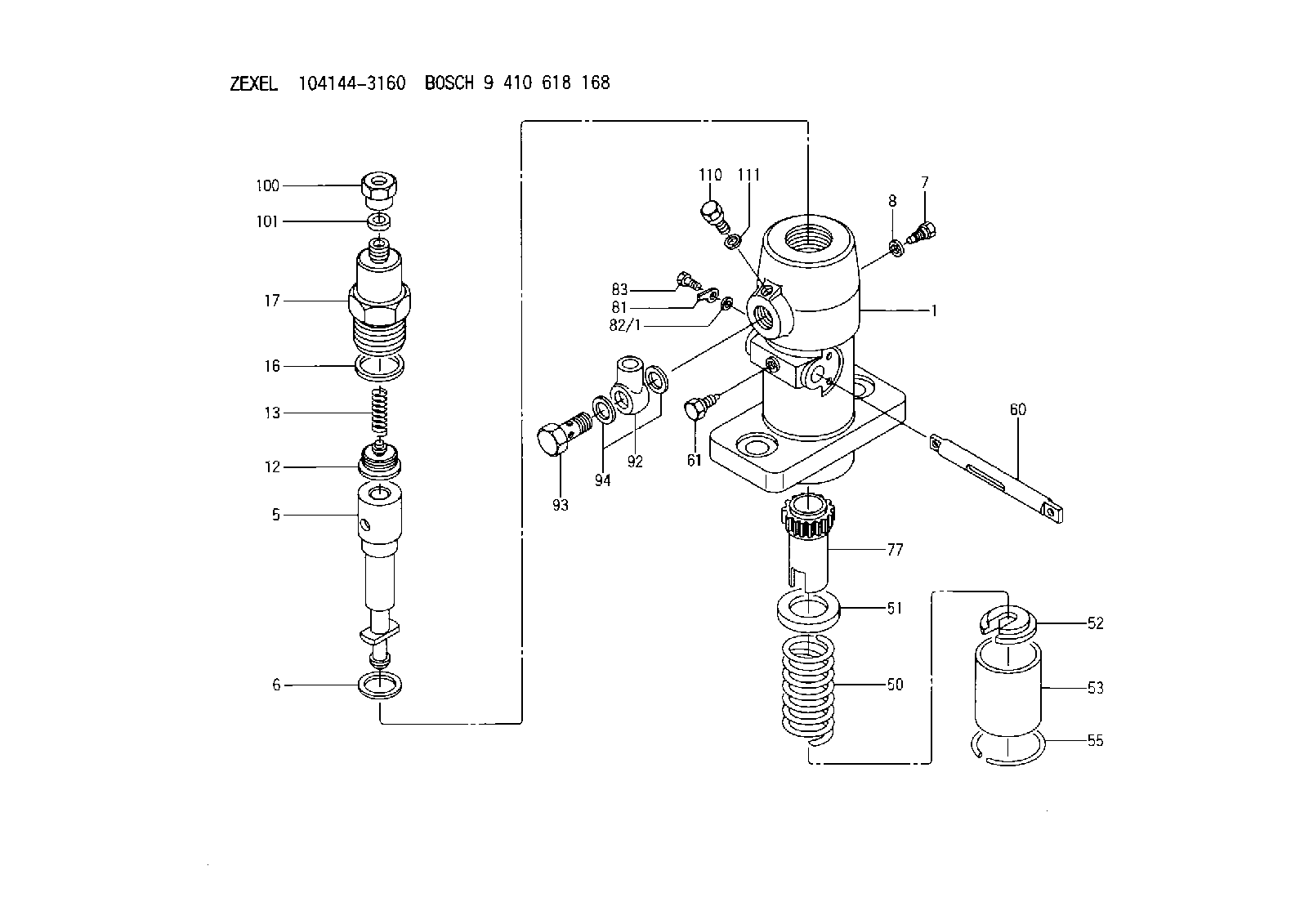
| 1. | [1] | 141051-7900 | PUMP HOUSING |
| 5. | [1] | 141170-1720 | PLUNGER-AND-BARREL ASSY C45 |
| 6. | [1] | 141162-0000 | GASKET |
| 7. | [1] | 141106-8000 | CAPSULE |
| 8. | [1] | 029340-8020 | GASKET |
| 12. | [1] | 141110-6820 | DELIVERY-VALVE ASSEMBLY C1 |
| 13. | [1] | 141112-0600 | COMPRESSION SPRING |
| 16. | [1] | 141115-0600 | GASKET |
| 17. | [1] | 141126-1300 | FITTING |
| 50. | [1] | 141215-0700 | COMPRESSION SPRING |
| 51. | [1] | 141216-2400 | SLOTTED WASHER |
| 52. | [1] | 141217-0300 | SLOTTED WASHER |
| 53. | [1] | 141218-4200 | GUIDE |
| 55. | [1] | 141220-0300 | LOCKING WASHER |
| 60. | [1] | 141230-7600 | CONTROL RACK |
| 61. | [1] | 141226-3100 | BLEEDER SCREW |
| 77. | [1] | 141241-0900 | CONTROL SLEEVE |
| 81. | [1] | 141245-2000 | POINTER |
| 82/1. | [0] | 023500-6210 | PLAIN WASHER D11&6.4T1.5 |
| 82/1. | [0] | 029300-6010 | PLAIN WASHER D11&6.4T0.8 |
| 82/1. | [0] | 029300-6020 | PLAIN WASHER D11&6.4T0.35 |
| 83. | [1] | 020006-1440 | BLEEDER SCREW |
| 92. | [1] | 027118-1540 | INLET UNION |
| 93. | [1] | 029731-8200 | EYE BOLT |
| 94. | [2] | 026518-2240 | GASKET |
| 100. | [1] | 029761-8190 | UNION NUT |
| 101. | [1] | 029351-0080 | PLAIN WASHER |
| 110. | [1] | 140420-0400 | FLAT-HEAD SCREW |
| 111. | [1] | 026506-1040 | GASKET |
Cross reference number
Zexel num
Bosch num
Firm num
Name
104144-3160
1C947004A
FUEL-INJECTION PUMP
K 24DA FUEL INJECTION PUMP PF-1C(D) PF
K 24DA FUEL INJECTION PUMP PF-1C(D) PF
Information:
Recommended Procedure With Chassis Dynamometer
Possible Causes/CorrectionsMinor Operating Faults
To help identify a problem before a more involved troubleshooting procedure is started, follow the procedure given in the Primary Engine Checks section.Fuel Ratio Control Out Of Adjustment Or Bad
Follow the procedure in the Testing and Adjusting section of this Service Manual.Check Engine Performance
Do a Power Analysis report (PAR), Level II, to check engine performance. See Special Instruction, Form No. SEHS8025 and SEHS7886 for the tooling and procedures to use. Be sure to make a record of the temperatures for inlet air, fuel (at filter base), lubricating oil and coolant.Fuel Settings Not Correct
If the Power Analysis Report indicates a problem, the governor fuel settings should be verified. See the Testing and Adjusting section of this Service Manual for the necessary procedures. Also, refer back to the information learned earlier (see Owner/Operator input section) about the truck specifications and application and judge whether or not the engine is performing as expected or customer expectation is realistic.Bad Fuel Nozzle(s)
Remove the fuel nozzles and test as in the Testing and Adjusting section of this Service Manual.Recommended Procedure Without Chassis Dynamometer
Possible Causes/CorrectionsMinor Operating Faults
To help identify a problem before a more involved troubleshooting procedure is started, follow the procedure given in the Primary Engine Checks section.Fuel Ratio Control Out Of Adjustment Or Bad
Follow the procedure in the Testing and Adjusting section of this Service Manual.Fuel Injection Timing Not Correct
Follow the procedures in the Testing and Adjusting section of this Service Manual.Check Engine Performance
Install the tooling and follow the procedure given in the Road Test section.Fuel Settings Not Correct
If the Road Test indicates a problem, the governor fuel settings should be verified. See the Testing and Adjusting section of this Service Manual for the necessary procedures. Also, refer back to the information learned earlier (see Owner Operator Input section) about the truck specifications and application and judge whether or not the engine is performing as expected or customer expectation is realistic.Any Further Diagnosis Must Be Done On A Chassis Dynamometer
If the fuel settings are correct and the above procedures have been followed without finding the problem a Power Analysis Report (PAR), Level II, must be done on the engine. See Special Instruction, Form Nos. SEHS8025 and SEHS7886 for the correct tools and procedures to use.
Possible Causes/CorrectionsMinor Operating Faults
To help identify a problem before a more involved troubleshooting procedure is started, follow the procedure given in the Primary Engine Checks section.Fuel Ratio Control Out Of Adjustment Or Bad
Follow the procedure in the Testing and Adjusting section of this Service Manual.Check Engine Performance
Do a Power Analysis report (PAR), Level II, to check engine performance. See Special Instruction, Form No. SEHS8025 and SEHS7886 for the tooling and procedures to use. Be sure to make a record of the temperatures for inlet air, fuel (at filter base), lubricating oil and coolant.Fuel Settings Not Correct
If the Power Analysis Report indicates a problem, the governor fuel settings should be verified. See the Testing and Adjusting section of this Service Manual for the necessary procedures. Also, refer back to the information learned earlier (see Owner/Operator input section) about the truck specifications and application and judge whether or not the engine is performing as expected or customer expectation is realistic.Bad Fuel Nozzle(s)
Remove the fuel nozzles and test as in the Testing and Adjusting section of this Service Manual.Recommended Procedure Without Chassis Dynamometer
Possible Causes/CorrectionsMinor Operating Faults
To help identify a problem before a more involved troubleshooting procedure is started, follow the procedure given in the Primary Engine Checks section.Fuel Ratio Control Out Of Adjustment Or Bad
Follow the procedure in the Testing and Adjusting section of this Service Manual.Fuel Injection Timing Not Correct
Follow the procedures in the Testing and Adjusting section of this Service Manual.Check Engine Performance
Install the tooling and follow the procedure given in the Road Test section.Fuel Settings Not Correct
If the Road Test indicates a problem, the governor fuel settings should be verified. See the Testing and Adjusting section of this Service Manual for the necessary procedures. Also, refer back to the information learned earlier (see Owner Operator Input section) about the truck specifications and application and judge whether or not the engine is performing as expected or customer expectation is realistic.Any Further Diagnosis Must Be Done On A Chassis Dynamometer
If the fuel settings are correct and the above procedures have been followed without finding the problem a Power Analysis Report (PAR), Level II, must be done on the engine. See Special Instruction, Form Nos. SEHS8025 and SEHS7886 for the correct tools and procedures to use.