Information fuel-injection pump
BOSCH
9 410 617 670
9410617670
ZEXEL
104144-0150
1041440150
Rating:
Components :
| 0. | INJECTION-PUMP ASSEMBLY | 104144-0150 |
| 1. | _ | |
| 2. | FUEL INJECTION PUMP | |
| 3. | NUMBER PLATE | |
| 4. | _ | |
| 5. | CAPSULE | |
| 6. | ADJUSTING DEVICE | |
| 7. | NOZZLE AND HOLDER ASSY | 105101-3290 |
| 8. | Nozzle and Holder | |
| 9. | Open Pre:MPa(Kqf/cm2) | 27.5{280} |
| 10. | NOZZLE-HOLDER | 105031-8020 |
| 11. | NOZZLE | 105010-1710 |
Scheme ###:
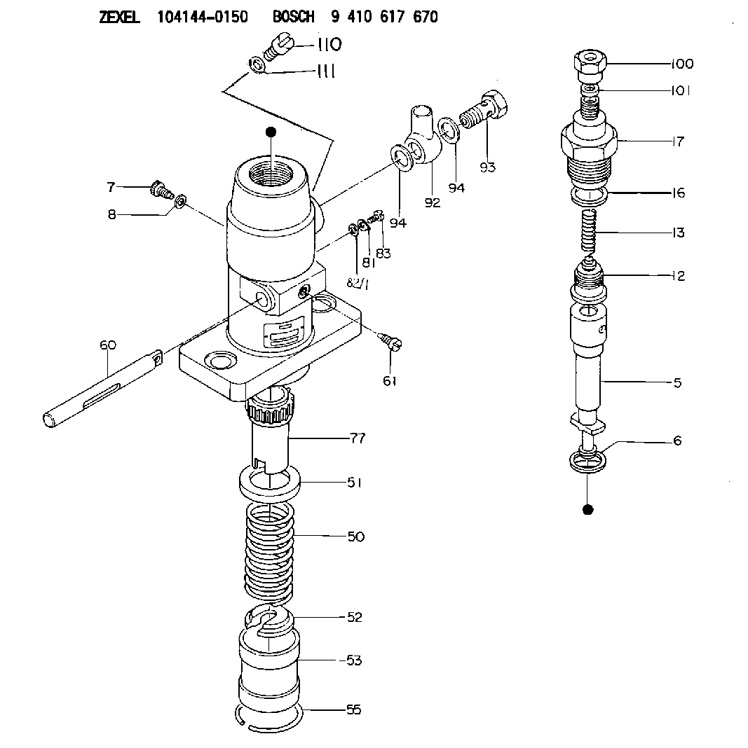
| 5. | [1] | 141170-0920 | PLUNGER-AND-BARREL ASSY |
| 6. | [1] | 029333-3010 | GASKET |
| 7. | [1] | 141106-8000 | CAPSULE |
| 8. | [1] | 029330-8050 | GASKET |
| 12. | [1] | 141110-1520 | DELIVERY-VALVE ASSEMBLY |
| 13. | [1] | 141112-0600 | COMPRESSION SPRING |
| 16. | [1] | 141115-0600 | GASKET |
| 17. | [1] | 141116-1500 | FITTING |
| 50. | [1] | 141215-0700 | COMPRESSION SPRING |
| 51. | [1] | 141216-2400 | SLOTTED WASHER |
| 52. | [1] | 141217-0300 | SLOTTED WASHER |
| 53. | [1] | 141218-4200 | GUIDE |
| 55. | [1] | 141220-0300 | LOCKING WASHER |
| 60. | [1] | 141244-1400 | CONTROL RACK |
| 61. | [1] | 141226-3100 | BLEEDER SCREW |
| 77. | [1] | 141241-0900 | CONTROL SLEEVE |
| 81. | [1] | 141245-2000 | POINTER |
| 82/1. | [0] | 023500-6210 | PLAIN WASHER D11&6.4T1.5 |
| 82/1. | [0] | 029300-6010 | PLAIN WASHER D11&6.4T0.8 |
| 82/1. | [0] | 029300-6020 | PLAIN WASHER D11&6.4T0.35 |
| 83. | [1] | 020006-1440 | BLEEDER SCREW M6P1L14 |
| 92. | [1] | 029701-8230 | INLET UNION |
| 93. | [1] | 029731-8200 | EYE BOLT |
| 94. | [2] | 026518-2240 | GASKET D21.9&18.2T1 |
| 94. | [2] | 026518-2240 | GASKET D21.9&18.2T1 |
| 100. | [1] | 029761-8210 | UNION NUT |
| 101. | [1] | 029351-0120 | PLAIN WASHER |
| 110. | [1] | 140420-0400 | FLAT-HEAD SCREW |
| 111. | [1] | 026506-1040 | GASKET D9.9&6.2T1 |
Cross reference number
Zexel num
Bosch num
Firm num
Name
104144-0150
FUEL-INJECTION PUMP
K 24DA FUEL INJECTION PUMP PF-1C(D) PF
K 24DA FUEL INJECTION PUMP PF-1C(D) PF
Information:
Battery
Never disconnect any charging unit circuit or battery circuit cable from battery when the charging unit is operated. A spark can cause an explosion from the flammable vapor mixture of hydrogen and oxygen that is released from the electrolyte through the battery outlets. Injury to personnel can be the result.
The battery circuit is an electrical load on the charging unit. The load is variable because of the condition of the charge in the battery. Damage to the charging unit can result if the connections (either positive or negative) between the battery and charging unit are broken while the charging unit is in operation. This is because the battery load is lost and there is an increase in charging voltage. High voltage can damage, not only the charging unit, but also the regulator and other electrical components.Use the 6V4930 Battery Load Tester, the 8T0900 Clamp-On Ammeter and the 6V7070 Multimeter to load test a battery that does not hold a charge when in use. See Special Instruction, Form No. SEHS8268 for the correct procedure and specification to use.Charging System
The condition of charge in the battery at each regular inspection will show if the charging system operates correctly. An adjustment is necessary when the battery is constantly in a low condition of charge or a large amount of water is needed (more than one ounce of water per cell per week or per every 100 service hours).When it is possible, make a test of the charging unit and voltage regulator on the engine, and use wiring and components that are a permanent part of the system. Off-engine (bench) testing will give a test of the charging unit and voltage regulator operation. This testing will give an indication of needed repair. After repairs are made, again make a test to give proof that the units are repaired to their original condition of operation.Before the start of on-engine testing, the charging system and battery must be checked as shown in the Steps that follow:1. Battery must be at least 75% (1.225 Sp Gr) fully charged and held tightly in place. The battery holder must not put too much stress on the battery.2. Cables between the battery, starter and engine ground must be the correct size. Wires and cables must be free of corrosion and have cable support clamps to prevent stress on battery connections (terminals).3. Leads, junctions, switches, and panel instruments that have direct relation to the charging circuit must give correct circuit control.4. Inspect the drive components for the charging unit to be sure they are free of grease and oil and have the ability to operate the charging unit.Alternator Regulator Adjustment (Delco-Remy)
When an alternator is charging the battery too much or not enough, the charging rate of the alternator should be checked. Make reference to the Specifications module to find all testing specifications for the alternators and regulators.
5N5692 Alternator
(1) Ground terminal. (2) Pulley nut.No adjustment can be made to change the rate of charge on the alternator regulators. If rate