Information fuel-injection pump
BOSCH
9 410 617 900
9410617900
ZEXEL
104143-3150
1041433150
YANMAR
15062351701
15062351701
Rating:
Components :
| 0. | INJECTION-PUMP ASSEMBLY | 104143-3150 |
| 1. | _ | |
| 2. | FUEL INJECTION PUMP | |
| 3. | NUMBER PLATE | |
| 4. | _ | |
| 5. | CAPSULE | |
| 6. | ADJUSTING DEVICE | |
| 7. | NOZZLE AND HOLDER ASSY | |
| 8. | Nozzle and Holder | |
| 9. | Open Pre:MPa(Kqf/cm2) | |
| 10. | NOZZLE-HOLDER | |
| 11. | NOZZLE |
Scheme ###:
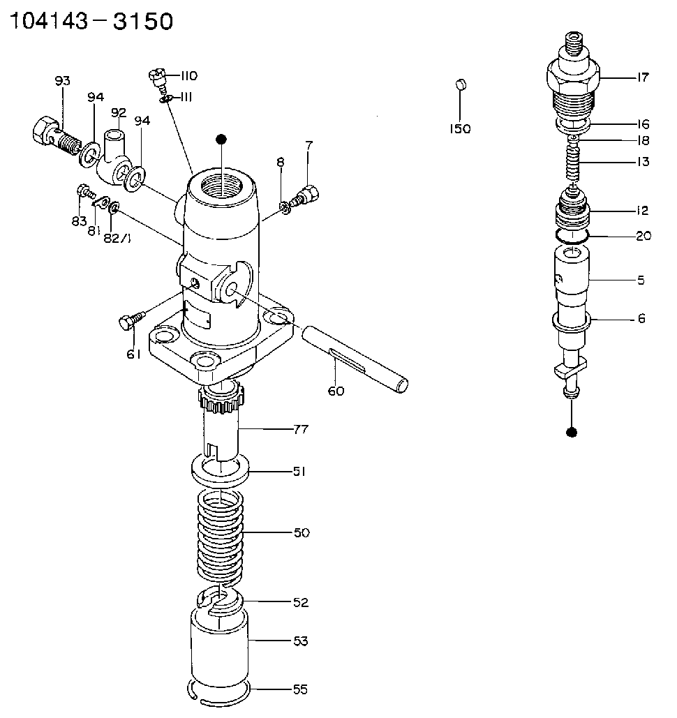
| 1. | [1] | 141051-5000 | PUMP HOUSING |
| 5. | [1] | 141170-0820 | PLUNGER-AND-BARREL ASSY |
| 6. | [1] | 029333-3010 | GASKET |
| 7. | [1] | 141106-8000 | CAPSULE |
| 8. | [1] | 029330-8050 | GASKET |
| 12. | [1] | 141110-5320 | DELIVERY-VALVE ASSEMBLY |
| 13. | [1] | 141112-2700 | COMPRESSION SPRING |
| 16. | [1] | 141115-4400 | GASKET |
| 17. | [1] | 141126-6900 | FITTING |
| 18. | [1] | 141117-4200 | FILLER PIECE |
| 20. | [1] | 029633-2040 | O-RING |
| 50. | [1] | 141215-2700 | COMPRESSION SPRING |
| 51. | [1] | 141216-2400 | SLOTTED WASHER |
| 52. | [1] | 141217-0300 | SLOTTED WASHER |
| 53. | [1] | 141218-4200 | GUIDE |
| 55. | [1] | 141220-0300 | LOCKING WASHER |
| 60. | [1] | 141230-9300 | CONTROL RACK |
| 61. | [1] | 141226-3100 | BLEEDER SCREW |
| 77. | [1] | 141241-0900 | CONTROL SLEEVE |
| 81. | [1] | 141245-2000 | POINTER |
| 82/1. | [0] | 023500-6210 | PLAIN WASHER D11&6.4T1.5 |
| 82/1. | [0] | 029300-6010 | PLAIN WASHER D11&6.4T0.8 |
| 82/1. | [0] | 029300-6020 | PLAIN WASHER D11&6.4T0.35 |
| 83. | [1] | 020006-1440 | BLEEDER SCREW M6P1L14 |
| 92. | [1] | 027118-1540 | INLET UNION |
| 93. | [1] | 029731-8200 | EYE BOLT |
| 94. | [2] | 026518-2240 | GASKET D21.9&18.2T1 |
| 94. | [2] | 026518-2240 | GASKET D21.9&18.2T1 |
| 110. | [1] | 140420-1800 | BLEEDER SCREW |
| 111. | [1] | 026506-1040 | GASKET D9.9&6.2T1 |
Cross reference number
Zexel num
Bosch num
Firm num
Name
104143-3150
15062351701 YANMAR
FUEL-INJECTION PUMP
K 24DA FUEL INJECTION PUMP PF-1C(D) PF
K 24DA FUEL INJECTION PUMP PF-1C(D) PF
104143-3150
15062351701C YANMAR
FUEL-INJECTION PUMP
A K 24DA FUEL INJECTION PUMP PF-1C(D) PF
A K 24DA FUEL INJECTION PUMP PF-1C(D) PF
Information:
(1) End play for shaft (new) ... 0.114 0.038 mm (.0045 .0015 in) Maximum permissible end play (worn) ... 0.20 mm (.008 in)(2) Thickness of thrust bearing (where thrust rings contact bearing) ... 5.36 0.03 mm (.211 .001 in)(3) Diameter of shaft (new) ... 15.997 to 16.005 mm (.6298 to .6301 in) Bore in the bearing (new) ... 16.035 to 16.043 mm (.6313 to .6316 in)Maximum permissible clearance between bearing and shaft (worn) ... 0.05 mm (.002 in)(4) Maximum permissible gap of oil seal ring, measured in bore of housing ... 0.25 mm (.010 in)(5) Install the compressor wheel (at room temperature) as follows: a. Put compressor wheel on the shaft.b. Put a small amount of clean engine oil on the threads.c. Tighten the nut to 14 to 17 N m (125 to 150 lb in).
Do not bend or add stress to the shaft when nut is loosened or tightened.
d. Remove nut from shaft and apply 6V1541 Quick Cure Primer on the threads of the shaft and nut followed by application of 9S3263 Retaining Compound.e. Tighten nut to 4 N m (30 lb in).f. Tighten nut more 90° rotation.(6) Thickness of each thrust ring ... 2.553 0.013 mm (.1005 .0005 in)(7) Bore in housing (new) ... 24.994 to 25.006 mm (.9840 to .9845 in) Outside diameter of the bearing (new) ... 24.882 to 24.892 mm (.9796 to .9800 in)Maximum permissible clearance between bearing and bore in housing (worn) ... 0.15 mm (.006 in)Tighten both band clamps (that hold the compressor and turbine housings to the cartridge group) with procedure that follows: a. Tighten to ... 14 1.1 N m (125 10 lb in)b. Tap (hit) clamp lightly all around.c. Tighten again to ... 14 1.1 N m (125 10 lb in)
Do not overtighten the clamps.
Torque for four nuts (put 5P3931 Anti-Seize Compound on threads) and bolts that hold turbocharger to exhaust manifold ... 55 5 N m (40 4 lb ft) Put clean engine oil in the oil inlet of the turbocharger after assembly or before installation to provide start up lubrication and/or storage protection.Turbocharger (S3B and C3B)
(1) End play for shaft (new) ... 0.102 0.025 mm (.004 .001 in) Maximum permissible end play (worn) ... 0.20 mm (.008 in)(2) Thickness of thrust bearing (where thrust rings contact bearing) ... 5.36 0.03 mm (.211 .001 in)(3) Diameter of shaft (new) ... 12.697 to 12.705 mm (.4999 to .5002 in) Bore in the bearing (new) ... 12.741 to 12.748 mm (.5016 to .5019 in)Maximum permissible clearance between bearing and shaft (worn) ... 0.05 mm (.002 in)(4) Maximum permissible gap of oil seal ring, measured in bore of housing ... 0.25 mm (.010 in)(5) Install the compressor wheel (at room temperature) as follows: a. Put compressor wheel on the shaft.b. Put a small amount of clean engine oil on the threads.c. Tighten the nut to 14 to 17 N m (125 to 150 lb