Information fuel-injection pump
BOSCH
9 410 617 448
9410617448
ZEXEL
104142-3520
1041423520
NIIGATA-URAWA
7H147010B
7h147010b
Rating:
Components :
| 0. | INJECTION-PUMP ASSEMBLY | 104142-3520 |
| 1. | _ | |
| 2. | FUEL INJECTION PUMP | |
| 3. | NUMBER PLATE | |
| 4. | _ | |
| 5. | CAPSULE | |
| 6. | ADJUSTING DEVICE | |
| 7. | NOZZLE AND HOLDER ASSY | |
| 8. | Nozzle and Holder | |
| 9. | Open Pre:MPa(Kqf/cm2) | |
| 10. | NOZZLE-HOLDER | |
| 11. | NOZZLE |
Scheme ###:
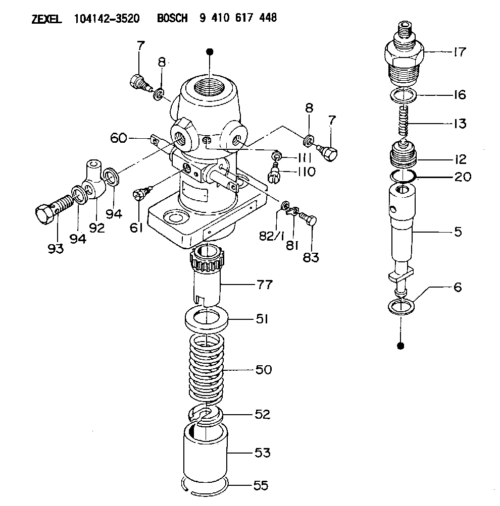
| 5. | [1] | 141170-4520 | PLUNGER-AND-BARREL ASSY |
| 6. | [1] | 141162-0000 | GASKET |
| 7. | [2] | 141106-8000 | CAPSULE |
| 7. | [2] | 141106-8000 | CAPSULE |
| 8. | [2] | 029330-8050 | GASKET |
| 8. | [2] | 029330-8050 | GASKET |
| 12. | [1] | 141140-3320 | DELIVERY-VALVE ASSEMBLY |
| 13. | [1] | 141112-2700 | COMPRESSION SPRING |
| 16. | [1] | 141115-4400 | GASKET |
| 17. | [1] | 141136-1620 | FITTING |
| 20. | [1] | 029633-2040 | O-RING |
| 50. | [1] | 141215-1900 | COMPRESSION SPRING |
| 51. | [1] | 141216-2400 | SLOTTED WASHER |
| 52. | [1] | 141217-1500 | SLOTTED WASHER |
| 53. | [1] | 141218-7400 | GUIDE |
| 55. | [1] | 141220-0300 | LOCKING WASHER |
| 60. | [1] | 141230-7300 | CONTROL RACK |
| 61. | [1] | 141226-3100 | BLEEDER SCREW |
| 77. | [1] | 141241-6300 | CONTROL SLEEVE |
| 81. | [1] | 141245-2000 | POINTER |
| 82/1. | [0] | 023500-6210 | PLAIN WASHER D11&6.4T1.5 |
| 82/1. | [0] | 029300-6010 | PLAIN WASHER D11&6.4T0.8 |
| 82/1. | [0] | 029300-6020 | PLAIN WASHER D11&6.4T0.35 |
| 83. | [1] | 020006-1440 | BLEEDER SCREW M6P1L14 |
| 92. | [1] | 027118-1540 | INLET UNION |
| 93. | [1] | 029731-8200 | EYE BOLT |
| 94. | [2] | 026518-2240 | GASKET D21.9&18.2T1 |
| 94. | [2] | 026518-2240 | GASKET D21.9&18.2T1 |
| 110. | [1] | 140420-1600 | BLEEDER SCREW |
| 111. | [1] | 026506-1040 | GASKET D9.9&6.2T1 |
Cross reference number
Zexel num
Bosch num
Firm num
Name
Information:
start by:a) remove oil pan1. Turn the crankshaft until two pistons are at bottom center. Remove connecting rod caps (1) from the two connecting rods. Remove the lower half of the bearings from the caps.2. Push the connecting rods away from the crankshaft and remove the upper half of the bearings.
Be careful not to damage the crankshaft journals. Do not turn the crankshaft while any of the connecting rod caps are removed.
Install the bearings dry when the clearance checks are made. Put clean engine oil on the bearings for final assembly.3. Clean the surfaces where the bearings fit. Install the upper half of the bearing in the connecting rod. Pull the connecting rod slowly on to the crankshaft.4. Install lower half of the bearing in the cap.
When the connecting rod caps are installed, make sure that the numbers on the side of the caps are next to and respective with the number on the side of the connecting rods.
Typical Example5. Check the bearing clearance with Plastigage (A). Put Plastigage (A) on the bearing.6. Put 2P2506 Thread Lubricant on the threads of the rod bolts and seat surfaces of the nuts.
Do not use an impact wrench to tighten the nuts the additional 60 5°.
Do not turn the crankshaft when Plastigage (A) is in position. 7. Put caps (1) in position on the connecting rods and install the nuts. Tighten the nuts to a torque of 40 4 N m (30 3 lb.ft.). Put a mark on each nut and the end of each bolt. Tighten the nuts 60 5° more.8. Remove the cap. Measure the thickness of Plastigage (A). The rod bearing clearance must be 0.053 to 0.140 mm (.0021 to .0055 in.). The maximum permissible clearance is 0.15 mm (.006 in.).9. Put the caps in position on the connecting rods and install the nuts. Tighten the nuts to a torque of 40 4 N m (30 3 lb.ft.). Put a mark on each nut and the end of each bolt. Tighten the nuts 60 5° more.10. Do Steps 1 through 9 again for other bearings. end by:a) install oil pan