Information fuel-injection pump
BOSCH
9 410 617 446
9410617446
ZEXEL
104142-3490
1041423490
NIIGATA-URAWA
7H147000C
7h147000c
Rating:
Components :
| 0. | INJECTION-PUMP ASSEMBLY | 104142-3490 |
| 1. | _ | |
| 2. | FUEL INJECTION PUMP | |
| 3. | NUMBER PLATE | |
| 4. | _ | |
| 5. | CAPSULE | |
| 6. | ADJUSTING DEVICE | |
| 7. | NOZZLE AND HOLDER ASSY | |
| 8. | Nozzle and Holder | |
| 9. | Open Pre:MPa(Kqf/cm2) | |
| 10. | NOZZLE-HOLDER | |
| 11. | NOZZLE |
Scheme ###:
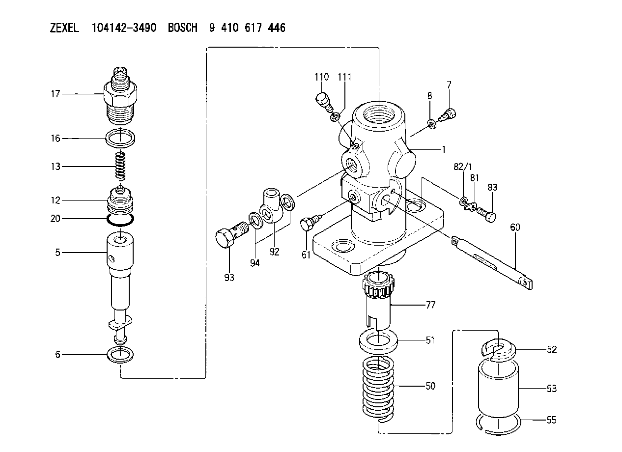
| 1. | [1] | 141052-3600 | PUMP HOUSING |
| 5. | [1] | 141170-3520 | PLUNGER-AND-BARREL ASSY |
| 6. | [1] | 141162-0000 | GASKET |
| 7. | [1] | 141106-8000 | CAPSULE |
| 8. | [1] | 029340-8020 | GASKET |
| 12. | [1] | 141140-5020 | DELIVERY-VALVE ASSEMBLY |
| 13. | [1] | 141112-2700 | COMPRESSION SPRING |
| 16. | [1] | 141115-4400 | GASKET |
| 17. | [1] | 141136-1620 | FITTING |
| 17/1. | [1] | 141136-1600 | FITTING |
| 17/2. | [1] | 141117-8600 | FILLER PIECE |
| 20. | [1] | 029633-2040 | O-RING |
| 50. | [1] | 141215-1900 | COMPRESSION SPRING |
| 51. | [1] | 141216-2400 | SLOTTED WASHER |
| 52. | [1] | 141217-1500 | SLOTTED WASHER |
| 53. | [1] | 141218-4200 | GUIDE |
| 55. | [1] | 141220-0300 | LOCKING WASHER |
| 60. | [1] | 141230-7300 | CONTROL RACK |
| 61. | [1] | 141226-3100 | BLEEDER SCREW |
| 77. | [1] | 141241-0900 | CONTROL SLEEVE |
| 81. | [1] | 141245-2000 | POINTER |
| 82/1. | [0] | 023500-6210 | PLAIN WASHER D11&6.4T1.5 |
| 82/1. | [0] | 029300-6010 | PLAIN WASHER D11&6.4T0.8 |
| 82/1. | [0] | 029300-6020 | PLAIN WASHER D11&6.4T0.35 |
| 83. | [1] | 020006-1440 | BLEEDER SCREW M6P1L14 |
| 92. | [1] | 027118-1540 | INLET UNION |
| 93. | [1] | 029731-8200 | EYE BOLT |
| 94. | [2] | 026518-2240 | GASKET D21.9&18.2T1 |
| 110. | [1] | 140420-1800 | BLEEDER SCREW |
| 111. | [1] | 026506-1040 | GASKET D9.9&6.2T1 |
Cross reference number
Zexel num
Bosch num
Firm num
Name
104142-3490
7H147000C NIIGATA-URAWA
FUEL-INJECTION PUMP
A K 24DA FUEL INJECTION PUMP PF-1C(D) PF
A K 24DA FUEL INJECTION PUMP PF-1C(D) PF
104142-3490
7H147000C NIIGATA-TEKKOU
FUEL-INJECTION PUMP
K 24DA FUEL INJECTION PUMP PF-1C(D) PF
K 24DA FUEL INJECTION PUMP PF-1C(D) PF
Information:
1. Remove carbon seal dam (2) with pliers. Remove compression seal (1). 2. Install a new compression seal on the nozzle. Install a new carbon seal dam with tool (B).3. Make sure the bore in the cylinder head and the fuel inlet fittings are clean.4. Install new O-ring seals on adapter (3) and fuel injection nozzle (4).5. Install the fuel injection nozzle in the head. Turn and push the nozzle into its correct position. Never put lubricant on the nozzle or bore in the cylinder head. 6. Install the adapter in the head. Connect the nozzle and fuel injection line to the adapter. Tighten the nuts to a torque of 40 7 N m (30 5 lb.ft.).7. Install the spacer and clamp (5) that hold the nozzle to the cylinder head. end by:a) install rocker shaftsDisassemble Fuel Injection Nozzles (9N3979 & 1W5829)
start by:a) remove fuel injection nozzles Do not disassemble any nozzle until test has shown it is needed. Check each nozzle with tool (A) for leakage, the pressure, at which the nozzle opens, and the shape and amount of fuel (spray pattern) that comes out of the nozzle. Do not clean or make an adjustment to any nozzle that has a large (excessive) amount of return leakage. Excessive return leakage can be an indication of nozzle failures that cannot be corrected with an adjustment or cleaning and can cause engine damage. See TESTING 9N3979 & 1W5829 FUEL INJECTION NOZZLES in TESTING AND ADJUSTING.
Keep the work area and all tools extra clean. Be careful not to cause damage to the parts while the nozzles are disassembled and assembled.
1. Remove cap (1) from the fuel injection nozzle.2. Put the nozzle in tool (B). Put tool (B) and the nozzle in a vise. Do not put any part of a nozzle directly in a vise. Loosen locknut (2) while the lift adjustment screw is held. Turn the lift adjustment screw (3) counterclockwise one turn. Hold the lift adjustment screw (3) with a 5/64" hex wrench and remove the locknut (2).
If the lift adjustment screw is not turned counterclockwise one turn, the valve can be bent or the seat for the valve can be damaged when the pressure adjustment screw is turned.
3. Loosen the locknut (4) that holds the pressure adjustment screw. Use tool (D) to hold the pressure adjustment screw. 4. While the nozzle is held in one hand, tilt the nozzle and remove the pressure adjusting screw and locknut, spring, seat and valve. 5. If the valve does not slide out of the nozzle, install tool (C) and remove valve as follows: a) Push valve into nozzle with tool (C) until valve is against bottom of nozzle.b) Push down on body of tool (C) to engage collet on valve with tool (C). c) Turn nut counterclockwise and remove valve from the nozzle body. Put the parts in solvent to loosen carbon and deposits of foreign material. The body is assembled with an epoxy material and must