Information fuel-injection pump
BOSCH
9 410 617 445
9410617445
ZEXEL
104142-3450
1041423450
NIIGATA-URAWA
7H647000B
7h647000b

Rating:
Components :
| 0. | INJECTION-PUMP ASSEMBLY | 104142-3450 |
| 1. | _ | |
| 2. | FUEL INJECTION PUMP | |
| 3. | NUMBER PLATE | |
| 4. | _ | |
| 5. | CAPSULE | |
| 6. | ADJUSTING DEVICE | |
| 7. | NOZZLE AND HOLDER ASSY | 105101-1940 |
| 8. | Nozzle and Holder | |
| 9. | Open Pre:MPa(Kqf/cm2) | 14.7{150} |
| 10. | NOZZLE-HOLDER | 105031-3490 |
| 11. | NOZZLE | 105000-0510 |
Scheme ###:
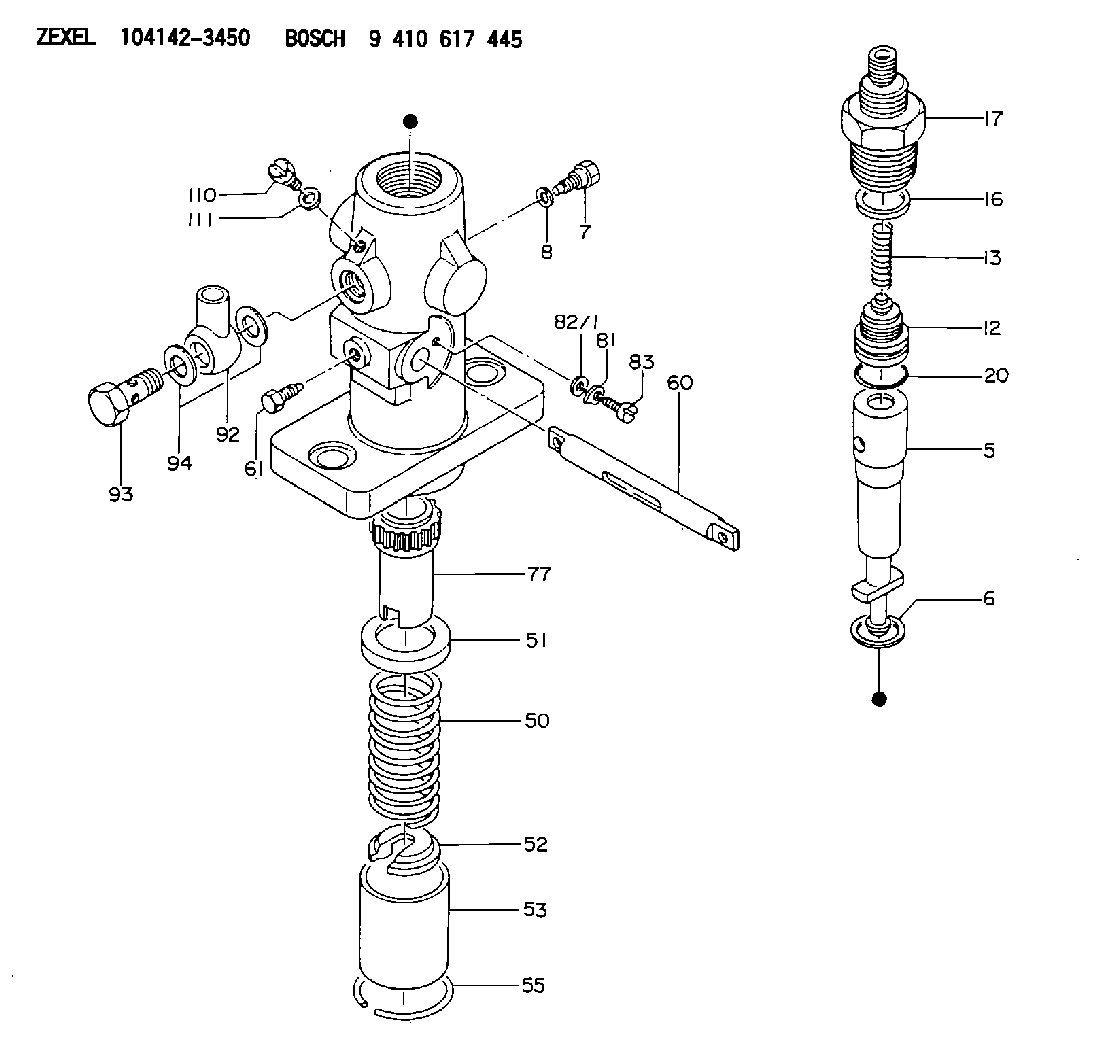
| 5. | [1] | 141170-3520 | PLUNGER-AND-BARREL ASSY |
| 6. | [1] | 141162-0000 | GASKET |
| 7. | [1] | 141106-8000 | CAPSULE |
| 8. | [1] | 029340-8020 | GASKET |
| 12. | [1] | 141140-3320 | DELIVERY-VALVE ASSEMBLY |
| 13. | [1] | 141112-2700 | COMPRESSION SPRING |
| 16. | [1] | 141115-4400 | GASKET |
| 17. | [1] | 141136-1620 | FITTING |
| 20. | [1] | 029633-2040 | O-RING |
| 50. | [1] | 141215-1900 | COMPRESSION SPRING |
| 51. | [1] | 141216-2400 | SLOTTED WASHER |
| 52. | [1] | 141217-1500 | SLOTTED WASHER |
| 53. | [1] | 141218-4200 | GUIDE |
| 55. | [1] | 141220-0300 | LOCKING WASHER |
| 60. | [1] | 141230-7300 | CONTROL RACK |
| 61. | [1] | 141226-3100 | BLEEDER SCREW |
| 77. | [1] | 141241-0900 | CONTROL SLEEVE |
| 81. | [1] | 141245-2000 | POINTER |
| 82/1. | [0] | 023500-6210 | PLAIN WASHER D11&6.4T1.5 |
| 82/1. | [0] | 029300-6010 | PLAIN WASHER D11&6.4T0.8 |
| 82/1. | [0] | 029300-6020 | PLAIN WASHER D11&6.4T0.35 |
| 83. | [1] | 020006-1440 | BLEEDER SCREW M6P1L14 |
| 92. | [1] | 027118-1540 | INLET UNION |
| 93. | [1] | 029731-8200 | EYE BOLT |
| 94. | [2] | 026518-2240 | GASKET D21.9&18.2T1 |
| 110. | [1] | 140420-1800 | BLEEDER SCREW |
| 111. | [1] | 026506-1040 | GASKET D9.9&6.2T1 |
Cross reference number
Zexel num
Bosch num
Firm num
Name
104142-3450
7H647000B NIIGATA-URAWA
FUEL-INJECTION PUMP
K 24DA FUEL INJECTION PUMP PF-1C(D) PF
K 24DA FUEL INJECTION PUMP PF-1C(D) PF
104142-3450
7H647000B NIIGATA-TEKKOU
FUEL-INJECTION PUMP
K 24DA FUEL INJECTION PUMP PF-1C(D) PF
K 24DA FUEL INJECTION PUMP PF-1C(D) PF
104142-3450
7H147000A
FUEL-INJECTION PUMP
K 24DA FUEL INJECTION PUMP PF-1C(D) PF
K 24DA FUEL INJECTION PUMP PF-1C(D) PF
Information:
start by:a) remove fuel injection pump housing and governor1. Install the fuel injection pump housing on tool (A). 2. Remove seven bolts (1) and governor housing (2). Later fuel injection pump housings have a thrust washer for the fuel injection pump camshaft. The thrust washer is behind the flange for the flyweights on the camshaft. To hold the thrust washer in place governor shaft (3) and the camshaft must be held in toward the fuel transfer pump any time sleeve (4) is removed. 3. Remove the plug from the cover and install tool (B) in the hole as shown. Turn the injection pump camshaft until tool (B) can be pushed into the groove (slot) in the camshaft. Any time the drive sleeve is removed from the camshaft a new one must be installed. The camshaft has serrations (splines) that cut grooves into the drive sleeve when it is installed to give a positive drive connection. If a formerly used drive sleeve is installed again it can slip (slide around) on the camshaft. 4. Install tool (C) in the threads of sleeve (4). Tighten the bolt until the sleeve can be removed. 5. Remove four bolts (5) and fuel transfer pump body (6) from the housing.6. Disconnect drain line (7) from the fitting on the back of fuel transfer pump body. 7. Remove gear (8) and O-ring seal (9) from the pump body. 8. Remove seals (10) from the pump body. 9. Remove drive gear (11) and the key from the camshaft. Install Fuel Transfer Pump
The fuel injection camshaft must be held in toward the fuel transfer pump during installation of the fuel transfer pump parts to hold the camshaft thrust washer in its counterbore. The thrust washer will be damaged when the sleeve is installed on the camshaft if it is not in the correct position. 1. Install key (1) and drive gear (2) on the shaft.2. Put No. 3 Aviation Permatex on the outside diameter of the seals for body (3). 3. Use tooling (B) to install the first seal in the body with the lip down and the second seal with the lip up. Install the first seal to a depth of 11.5 mm (.453 in.) and the second seal to a depth of 0.75 mm (.030 in.).4. Remove the extra permatex from the body and seals after installation. Be sure the drain hole between the seals is open. 5. Install O-ring seal (4) and gear (5) on the body. 6. Install tool (C) in the end of the fuel injection pump camshaft. Connect drain line (6) to the fitting on the back of the body and put the body in position on the fuel injection pump housing. Install the bolts that hold the body in place.7. Install tool (E) in the camshaft so it will not turn.8. Put a new sleeve (7) on the camshaft. A new drive sleeve must be installed because a used drive sleeve can slip (slide around) on the camshaft.9. Tighten
The fuel injection camshaft must be held in toward the fuel transfer pump during installation of the fuel transfer pump parts to hold the camshaft thrust washer in its counterbore. The thrust washer will be damaged when the sleeve is installed on the camshaft if it is not in the correct position. 1. Install key (1) and drive gear (2) on the shaft.2. Put No. 3 Aviation Permatex on the outside diameter of the seals for body (3). 3. Use tooling (B) to install the first seal in the body with the lip down and the second seal with the lip up. Install the first seal to a depth of 11.5 mm (.453 in.) and the second seal to a depth of 0.75 mm (.030 in.).4. Remove the extra permatex from the body and seals after installation. Be sure the drain hole between the seals is open. 5. Install O-ring seal (4) and gear (5) on the body. 6. Install tool (C) in the end of the fuel injection pump camshaft. Connect drain line (6) to the fitting on the back of the body and put the body in position on the fuel injection pump housing. Install the bolts that hold the body in place.7. Install tool (E) in the camshaft so it will not turn.8. Put a new sleeve (7) on the camshaft. A new drive sleeve must be installed because a used drive sleeve can slip (slide around) on the camshaft.9. Tighten