Information fuel-injection pump
BOSCH
9 410 617 857
9410617857
ZEXEL
104142-3440
1041423440
FUJI-DIESEL
A33366
a33366
Rating:
Components :
| 0. | INJECTION-PUMP ASSEMBLY | 104142-3440 |
| 1. | _ | |
| 2. | FUEL INJECTION PUMP | |
| 3. | NUMBER PLATE | |
| 4. | _ | |
| 5. | CAPSULE | |
| 6. | ADJUSTING DEVICE | |
| 7. | NOZZLE AND HOLDER ASSY | |
| 8. | Nozzle and Holder | |
| 9. | Open Pre:MPa(Kqf/cm2) | |
| 10. | NOZZLE-HOLDER | 105033-6400 |
| 11. | NOZZLE | 105011-0890 |
Scheme ###:
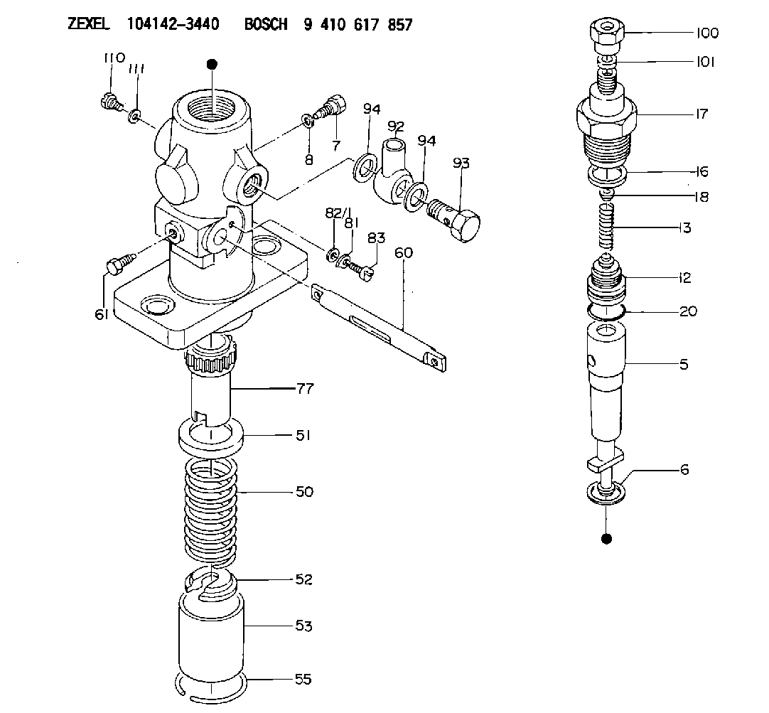
| 5. | [1] | 141170-1520 | PLUNGER-AND-BARREL ASSY |
| 6. | [1] | 029333-3010 | GASKET |
| 7. | [1] | 141106-8000 | CAPSULE |
| 8. | [1] | 029340-8020 | GASKET |
| 12. | [1] | 141110-5320 | DELIVERY-VALVE ASSEMBLY |
| 13. | [1] | 141112-0600 | COMPRESSION SPRING |
| 16. | [1] | 141115-4400 | GASKET |
| 17. | [1] | 141126-1000 | FITTING |
| 18. | [1] | 141117-3400 | SLOTTED WASHER |
| 20. | [1] | 029633-2040 | O-RING |
| 50. | [1] | 141215-0700 | COMPRESSION SPRING |
| 51. | [1] | 141216-2400 | SLOTTED WASHER |
| 52. | [1] | 141217-0300 | SLOTTED WASHER |
| 53. | [1] | 141218-4400 | GUIDE |
| 55. | [1] | 141220-0300 | LOCKING WASHER |
| 60. | [1] | 141243-8300 | CONTROL RACK |
| 61. | [1] | 141226-3100 | BLEEDER SCREW |
| 77. | [1] | 141241-0900 | CONTROL SLEEVE |
| 81. | [1] | 141245-2000 | POINTER |
| 82/1. | [0] | 023500-6210 | PLAIN WASHER D11&6.4T1.5 |
| 82/1. | [0] | 029300-6010 | PLAIN WASHER D11&6.4T0.8 |
| 82/1. | [0] | 029300-6020 | PLAIN WASHER D11&6.4T0.35 |
| 83. | [1] | 020006-1440 | BLEEDER SCREW M6P1L14 |
| 92. | [1] | 027118-1540 | INLET UNION |
| 93. | [1] | 029731-8200 | EYE BOLT |
| 94. | [2] | 026518-2240 | GASKET D21.9&18.2T1 |
| 94. | [2] | 026518-2240 | GASKET D21.9&18.2T1 |
| 100. | [1] | 029761-8210 | UNION NUT |
| 101. | [1] | 029350-8020 | PLAIN WASHER |
| 110. | [1] | 140420-1800 | BLEEDER SCREW |
| 111. | [1] | 026506-1040 | GASKET D9.9&6.2T1 |
Cross reference number
Zexel num
Bosch num
Firm num
Name
A33366 FUJI-DIESEL
FUEL-INJECTION PUMP
K 24DA FUEL INJECTION PUMP PF-1C(D) PF
K 24DA FUEL INJECTION PUMP PF-1C(D) PF
Information:
Before any service work is done on the fuel system, the outer surface of the injection pump housing must be clean.
The fuel injection pump housing and governor has been removed from the engine for illustration purposes. 1. Remove flange (1) and the flange assembly from the cover.2. Remove cover (2) from the pump housing. 3. Remove the bypass valve (3) and springs from the pump housing.4. Install tooling (A) on the fuel injection pump and loosen the bushing from the pump housing. Do not loosen screws (4) that hold the levers to the shaft when the pumps are removed or installed. If the levers are moved, fuel pump calibration will be changed. 5. Remove the fuel injection pump (5) from the pump housing. The sleeve on the plunger will slide off the lever as the pump is removed.6. Do Steps 4 and 5 for the remainder of the pumps.Install Fuel Injection Pumps
1. Turn the camshaft until the lifter for the pump to be installed is at its lowest position.2. Install the fuel injection pump (1) in the bore of the pump housing. 3. The sleeve (2) will be engaged with the lever when the pump is installed correctly.
If the levers have been moved on the shaft, fuel pump calibration must be made. (See TESTING AND ADJUSTING).
4. Tighten the bushing with tooling (A) to a torque of 80 7 N m (60 5 lb.ft.).5. Do Steps 1 through 4 for the remainder of the pumps. 6. Install the bypass valve and spring (3) in the pump housing.7. Install the cover (5) on the pump housing. Be sure the spring (3) is in the bore in the cover. 8. Install the flange (4) and the flange assembly on the cover.Disassemble Fuel Injection Pumps
1. Remove bushing (1) and O-ring seal (7) from bonnet (2).2. Remove ring (3) from the bonnet and barrel (4). 3. Remove check valve assembly (9) and spring (8) from the bonnet.4. Remove spring (10) and retainer washer (5).
Keep the plunger and sleeve with their respective barrel for installation. Do not use plungers, sleeves and barrels with other plungers, sleeves and barrels.
5. Remove plunger (11) and sleeve (6).Assemble Fuel Injection Pumps
1. Install the sleeve (4), plunger (5), spring (2) and washer (3) on barrel (1).
Be sure the sleeve and plunger are installed in their original barrel and the large hole in the plunger is up. The sleeve must be installed with the thin flange up.
2. Install the check valve assembly and spring in the bonnet. Connect the barrel and bonnet with the ring. Install the seal and bushing on the bonnet. end by:a) install fuel injection pumps