Information fuel-injection pump
BOSCH
9 410 618 165
9410618165
ZEXEL
104142-3350
1041423350
KUBOTA
2612603204
2612603204
Rating:
Components :
| 0. | INJECTION-PUMP ASSEMBLY | 104142-3350 |
| 1. | _ | |
| 2. | FUEL INJECTION PUMP | |
| 3. | NUMBER PLATE | |
| 4. | _ | |
| 5. | CAPSULE | |
| 6. | ADJUSTING DEVICE | |
| 7. | NOZZLE AND HOLDER ASSY | |
| 8. | Nozzle and Holder | |
| 9. | Open Pre:MPa(Kqf/cm2) | |
| 10. | NOZZLE-HOLDER | |
| 11. | NOZZLE | 105011-1650 |
Scheme ###:
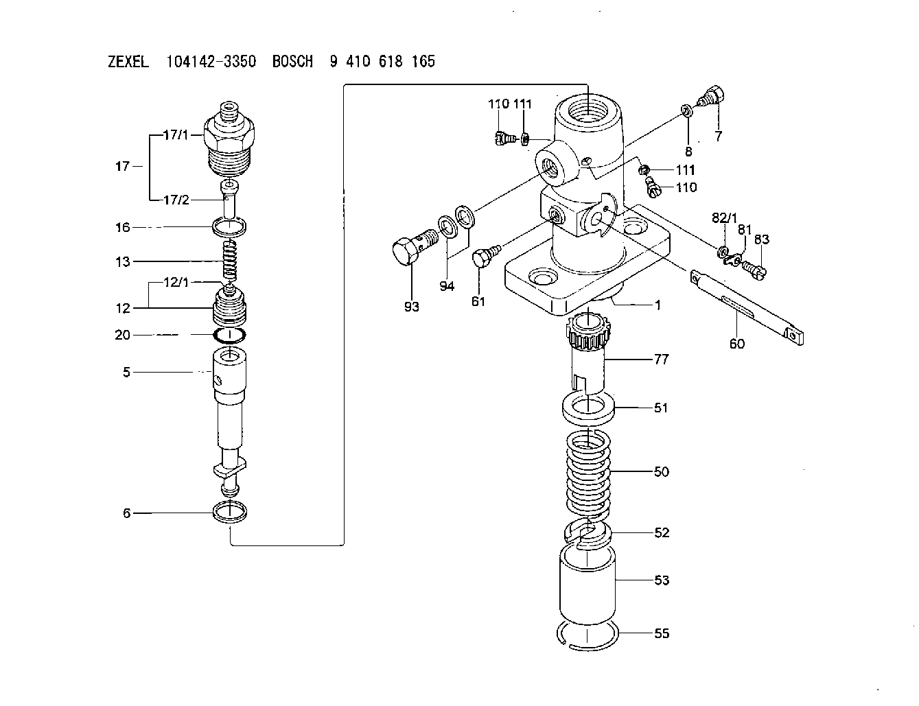
| 1. | [1] | 141051-8100 | PUMP HOUSING |
| 2. | [1] | 141117-0600 | FILLER PIECE |
| 5. | [1] | 141170-0220 | PLUNGER-AND-BARREL ASSY |
| 6. | [1] | 029333-3010 | GASKET |
| 7. | [1] | 141106-9300 | CAPSULE |
| 8. | [1] | 029330-8050 | GASKET |
| 12. | [1] | 141110-5320 | DELIVERY-VALVE ASSEMBLY |
| 12/1. | [1] | 141110-5300 | VALVE BODY |
| 13. | [1] | 141112-3000 | COMPRESSION SPRING |
| 16. | [1] | 141115-4400 | GASKET |
| 17. | [1] | 141137-0420 | FITTING |
| 17/1. | [1] | 141137-0000 | FITTING |
| 17/2. | [1] | 141117-0600 | FILLER PIECE |
| 20. | [1] | 029633-2040 | O-RING |
| 50. | [1] | 141215-0700 | COMPRESSION SPRING |
| 51. | [1] | 141216-2400 | SLOTTED WASHER |
| 52. | [1] | 141217-0300 | SLOTTED WASHER |
| 53. | [1] | 141218-4200 | GUIDE |
| 55. | [1] | 141220-0300 | LOCKING WASHER |
| 60. | [1] | 141230-7300 | CONTROL RACK |
| 61. | [1] | 141226-2100 | FLAT-HEAD SCREW |
| 77. | [1] | 141241-0900 | CONTROL SLEEVE |
| 81. | [1] | 141245-2000 | POINTER |
| 82/1. | [0] | 023500-6210 | PLAIN WASHER D11&6.4T1.5 |
| 82/1. | [0] | 029300-6010 | PLAIN WASHER D11&6.4T0.8 |
| 82/1. | [0] | 029300-6020 | PLAIN WASHER D11&6.4T0.35 |
| 83. | [1] | 020006-1440 | BLEEDER SCREW M6P1L14 |
| 93. | [1] | 029731-8200 | EYE BOLT |
| 94. | [2] | 026518-2240 | GASKET D21.9&18.2T1 |
| 110. | [2] | 141420-0400 | BLEEDER SCREW |
| 110. | [2] | 141420-0400 | BLEEDER SCREW |
| 111. | [2] | 026506-1040 | GASKET D9.9&6.2T1 |
| 111. | [2] | 026506-1040 | GASKET D9.9&6.2T1 |
Cross reference number
Zexel num
Bosch num
Firm num
Name
Information:
start by:a) remove turbocharger 1. Make a mark on compressor housing (1), cartridge assembly (3) and the turbine housing (4) for correct installation. 2. Loosen clamp assembly (2). Remove compressor housing (1) and cartridge assembly (3) from the turbine housing.3. Remove bolts (6) and plates (5) that hold cartridge assembly in the compressor housing. Remove cartridge assembly (3). 4. Remove O-ring seal (7) from the cartridge assembly. 5. Put cartridge assembly (3) in position in tooling (A) and loosen nut on the compressor wheel with tooling (C).6. Remove nut (8) and the compressor wheel (9). 7. Remove shaft and wheel assembly (10) from the cartridge assembly. 8. Remove shroud (11) from the cartridge assembly. 9. Remove four bolts (12) and then remove backplate (13) from the cartridge assembly.10. Remove spacer (14) from the backplate. 11. Remove two seal rings (15) from the spacer. 12. Remove snap ring (16) from cartridge housing with tool (B). 13. Remove bearing (17) and rings from the cartridge housing.14. Remove snap ring (18) from cartridge housing with tool (B). 15. Turn the cartridge housing over and then remove screws (20), plate (21) and collar (19). 16. Remove bearing (22) from the cartridge housing. 17. Remove snap ring (23) from the cartridge housing with tool (B).Assemble Turbocharger
Make sure all of the oil passages in the turbocharger cartridge housing are clean and free of dirt and foreign material. Put clean engine oil on all parts of the cartridge assembly. 1. Install snap ring (1) in the cartridge housing with tool (A). Make sure the oil hole in plate (5) is open and clean to prevent a bearing failure.2. Install bearing (2), collars (3), plate (5) and screws (4). Tighten the screws to
Make sure all of the oil passages in the turbocharger cartridge housing are clean and free of dirt and foreign material. Put clean engine oil on all parts of the cartridge assembly. 1. Install snap ring (1) in the cartridge housing with tool (A). Make sure the oil hole in plate (5) is open and clean to prevent a bearing failure.2. Install bearing (2), collars (3), plate (5) and screws (4). Tighten the screws to