Information fuel-injection pump
BOSCH
9 410 617 313
9410617313
ZEXEL
104142-0180
1041420180
KUBOTA
2012605243
2012605243

Rating:
Components :
| 0. | INJECTION-PUMP ASSEMBLY | 104142-0180 |
| 1. | _ | |
| 2. | FUEL INJECTION PUMP | |
| 3. | NUMBER PLATE | |
| 4. | _ | |
| 5. | CAPSULE | |
| 6. | ADJUSTING DEVICE | |
| 7. | NOZZLE AND HOLDER ASSY | |
| 8. | Nozzle and Holder | |
| 9. | Open Pre:MPa(Kqf/cm2) | |
| 10. | NOZZLE-HOLDER | |
| 11. | NOZZLE |
Scheme ###:
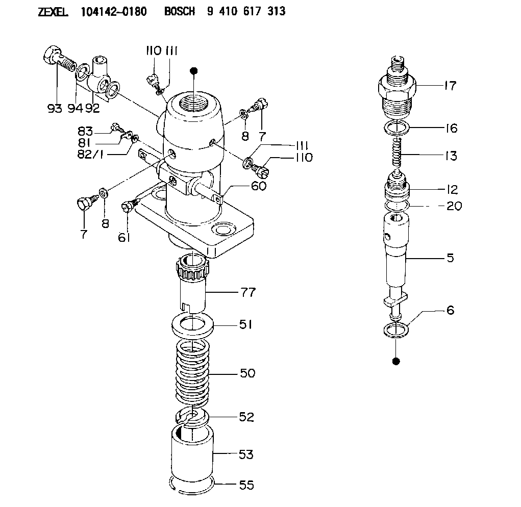
| 5. | [1] | 141170-2720 | PLUNGER-AND-BARREL ASSY |
| 6. | [1] | 029333-3010 | GASKET |
| 7. | [2] | 141106-8000 | CAPSULE |
| 7. | [2] | 141106-8000 | CAPSULE |
| 8. | [2] | 029340-8020 | GASKET |
| 8. | [2] | 029340-8020 | GASKET |
| 12. | [1] | 141110-2020 | DELIVERY-VALVE ASSEMBLY |
| 13. | [1] | 141112-9700 | COMPRESSION SPRING |
| 16. | [1] | 141115-4400 | GASKET |
| 17. | [1] | 141137-0020 | FITTING |
| 20. | [1] | 029633-2040 | O-RING |
| 50. | [1] | 141215-3500 | COMPRESSION SPRING |
| 51. | [1] | 141216-0500 | SLOTTED WASHER |
| 52. | [1] | 141217-0300 | SLOTTED WASHER |
| 53. | [1] | 141218-4200 | GUIDE |
| 55. | [1] | 141220-0300 | LOCKING WASHER |
| 60. | [1] | 141230-8300 | CONTROL RACK |
| 61. | [1] | 141226-3100 | BLEEDER SCREW |
| 77. | [1] | 141241-0900 | CONTROL SLEEVE |
| 81. | [1] | 141245-2000 | POINTER |
| 82/1. | [0] | 023500-6210 | PLAIN WASHER D11&6.4T1.5 |
| 82/1. | [0] | 029300-6010 | PLAIN WASHER D11&6.4T0.8 |
| 82/1. | [0] | 029300-6020 | PLAIN WASHER D11&6.4T0.35 |
| 83. | [1] | 020006-1440 | BLEEDER SCREW M6P1L14 |
| 92. | [1] | 029701-8270 | INLET UNION |
| 93. | [1] | 029731-8200 | EYE BOLT |
| 94. | [2] | 026518-2240 | GASKET D21.9&18.2T1 |
| 110. | [1] | 140420-1800 | BLEEDER SCREW |
| 110. | [1] | 140420-1800 | BLEEDER SCREW |
| 111. | [1] | 026506-1040 | GASKET D9.9&6.2T1 |
| 111. | [1] | 026506-1040 | GASKET D9.9&6.2T1 |
Cross reference number
Zexel num
Bosch num
Firm num
Name
104142-0180
2012605243 KUBOTA
FUEL-INJECTION PUMP
K 24DA FUEL INJECTION PUMP PF-1C(D) PF
K 24DA FUEL INJECTION PUMP PF-1C(D) PF
104142-0180
2012605245 KUBOTA
FUEL-INJECTION PUMP
A K 24DA FUEL INJECTION PUMP PF-1C(D) PF
A K 24DA FUEL INJECTION PUMP PF-1C(D) PF
104142-0180
2012605246 KUBOTA
FUEL-INJECTION PUMP
B K 24DA FUEL INJECTION PUMP PF-1C(D) PF
B K 24DA FUEL INJECTION PUMP PF-1C(D) PF
104142-0180
2012605246 KUBOTA
FUEL-INJECTION PUMP
K 24DA FUEL INJECTION PUMP PF-1C(D) PF
K 24DA FUEL INJECTION PUMP PF-1C(D) PF
Information:
2. Put transmission in direct gear and the differential in the highest speed ratio. Operate vehicle at maximum engine speed and increase chassis dynamometer load until a speed of 50 rpm less than rated speed is reached (continuity light should be on). Maintain this speed for one minute and record the engine speed and wheel horsepower. If horsepower is low and poor maintenance is suspected, remove air cleaner and check horsepower again to see if a plugged air cleaner could be the problem.3a. If the wheel horsepower is correct, find the set point (balance point) of the engine (speed at which the load stop pin just touches the torque spring or stop bar). At this point the continuity light should flicker (go off and on dimly).If the set point (balance point) is correct, then the low power complaint cannot be validated. No further test or repairs are necessary.If the set point (balance point) is low, see Procedure No. 4.3b. If the wheel horsepower is below the correct value, find the set point (balance point) of the engine (speed at which the load stop pin just touches the torque spring or stop bar). At this point the continuity light should flicker (go off and on dimly).If the set point (balance point) is correct, see Procedure No. 5.If the set point (balance point) is low, see Procedure No. 4.4. If the set point (balance point) is low, the high idle will have to be increased to raise the set point (balance point) to the correct rpm (the point at which the continuity light just comes on). If the set point (balance point) is still low and high idle has been adjusted to maximum, disengage clutch while maximum throttle position is maintained. Now observe high idle rpm and, if lower than previously adjusted, check frame-to-engine-mount. A damaged or loose engine mount may put the linkage in a bind and prevent maximum governor position at load conditions.5. If the set point (balance point) was correct and the wheel horsepower was low, install the 1U5470 Engine Pressure Group and do the wheel horsepower test again as shown in Procedure No 2.At full load rpm, measure the boost and the fuel pressure. See Fuel Setting and Related Information Fiche to find the correct boost pressure for a particular engine (since the engine is in vehicle, be sure to make reference to the General Notes in the Fuel Setting and Related Information Fiche to determine the correct boost pressure with air cleaner and muffler installed). If boost is low, check connections ahead of turbine side of turbocharger for exhaust leaks and connections after compressor side of turbocharger for inlet air leaks.6. Check the air inlet restriction and exhaust back pressure.Air flow through the air cleaner and piping must not have a vacuum restriction (negative pressure difference between atmospheric air and air that has gone through air cleaner) of more than 635 mm (25 in) of water. Back pressure from the exhaust (pressure difference measurement between